Efficient Atmospheric Pressure Interface for Mass Spectrometers and Method

a mass spectrometer and atmospheric pressure technology, applied in the direction of isotope separation, electric discharge lamps, particle separator tubes, etc., can solve the problems of reducing the number of ions delivered to the mass analyzer, significant loss in the existing ion transfer arrangement. , to achieve the effect of reducing the energy with which the ion bearing is carried, reducing the flow of gas, and reducing the energy

Active Publication Date: 2010-02-18
THERMO FISHER SCI BREMEN
View PDF10 Cites 11 Cited by
  • Summary
  • Abstract
  • Description
  • Claims
  • Application Information

AI Technical Summary

Benefits of technology

[0023]The embodiments of the present invention have the advantage of reduced flow of gas through an exit end of the ion transfer tube. Several associated advantages have also been postulated. For example, the reduced flow through the exit end of the ion transfer tube decreases the energy with which the ion bearing gas expands as it leaves the ion transfer tube. Thus, the ions have a greater chance of traveling on a straight line through an aperture of a skimmer immediately downstream. Also, reduction of the flow in at least a portion of the ion transfer tube may have the effect of increasing the amount of laminar flow in that portion of the ion transfer tube. Laminar flow is more stable so that the ions can remain focused and travel in a straight line for passage through the relatively small aperture of a skimmer. With gas being pumped out through a sidewall of the ion transfer tube, the pressure inside the ion transfer tube is reduced. Reduced pressure can cause increased desolvation. Furthermore, latent heat is removed when the gas is pumped out through the sidewall. Hence, more heat may be transferred through the ion transfer tube and into the sample remaining in the interior region resulting in increased desolvation and increased numbers of ions actually reaching the ion optics.

Problems solved by technology

There is a significant loss in existing ion transfer arrangements, so that the majority of those ions generated by the ion source do not succeed in reaching and passing through the ion transfer arrangement into the subsequent stages of mass spectrometry.
This diminishes the number of ions delivered to the mass analyzer and adversely affects instrument sensitivity.
Furthermore, for tubes constructed of a dielectric material, collision of ions with the tube wall may result in charge accumulation and inhibit ion entry to and flow through the tube.
Unfortunately, effective operation of ion funnel extends only up to gas pressures of approximately 40 mbar, i.e 4% of atmospheric pressure.
However, it does not address the issue of focusing ions in the pressure region between atmospheric and forevacuum.
Though this is likely to help reducing ion losses, actual focusing of ions towards the central axis would require ever increasing axial field which is becomes technically impossible at low pressures because of breakdown.
While some of the foregoing approaches may be partially successful for reducing ion loss and / or alleviating adverse effects arising from ion collisions with the tube wall, the focusing force is far from sufficient for keeping ions away from the walls, especially given significant space charge within the ion beam and significant length of the tube.
However, gas velocity is significantly lower in this region than inside the tube and therefore space charge effects produce higher losses.

Method used


Image

  • Efficient Atmospheric Pressure Interface for Mass Spectrometers and Method
  • Efficient Atmospheric Pressure Interface for Mass Spectrometers and Method
  • Efficient Atmospheric Pressure Interface for Mass Spectrometers and Method

Examples


Embodiment Construction

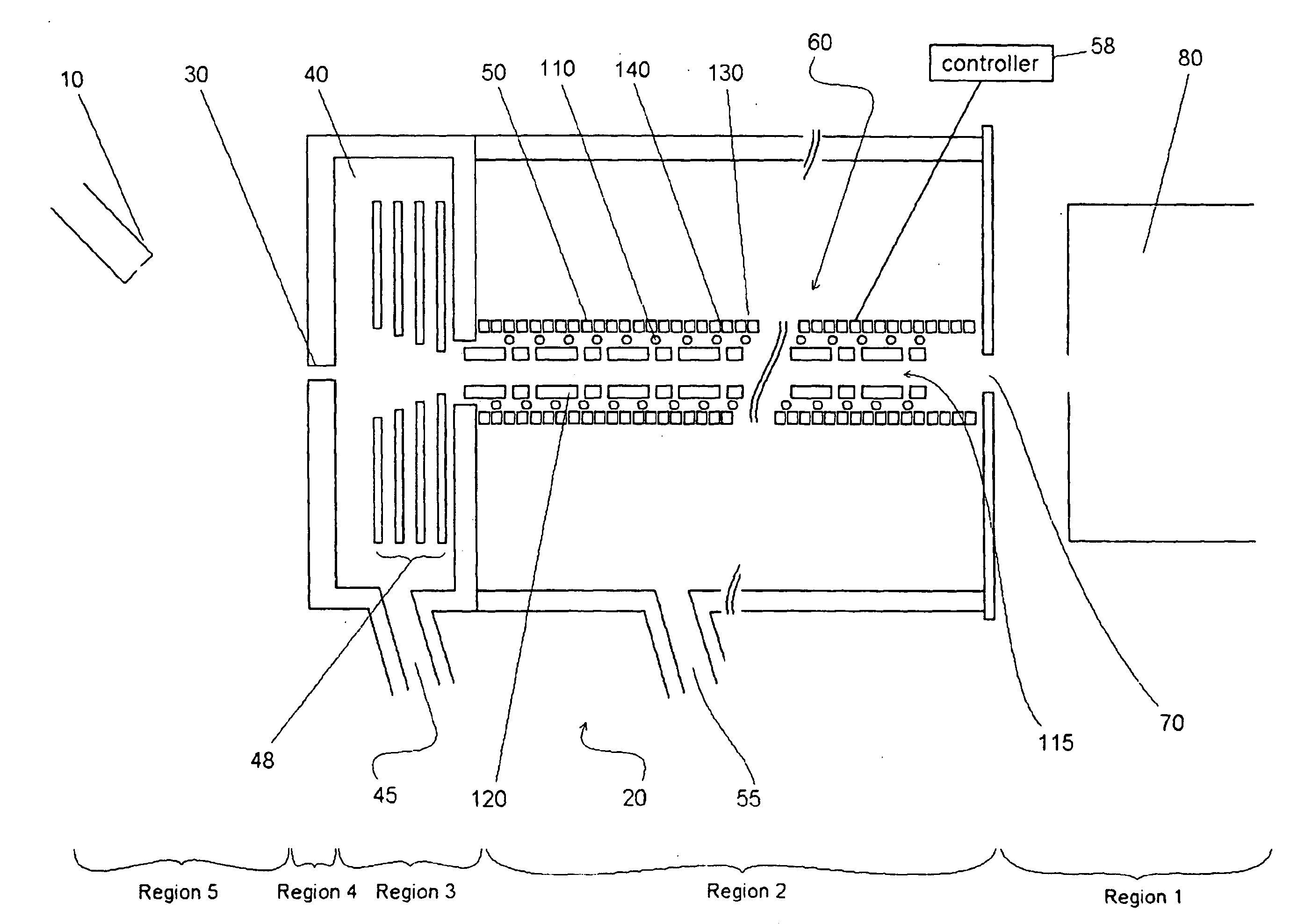
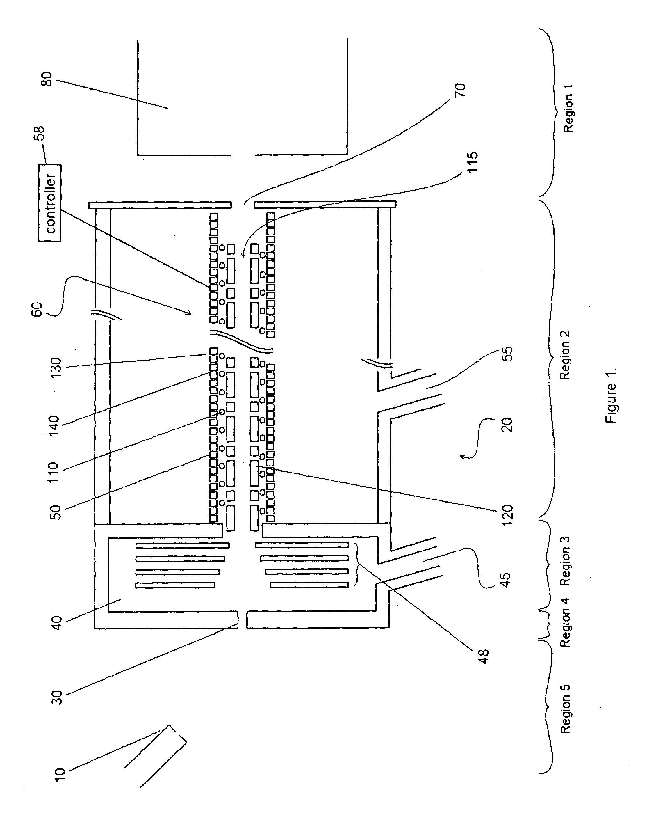
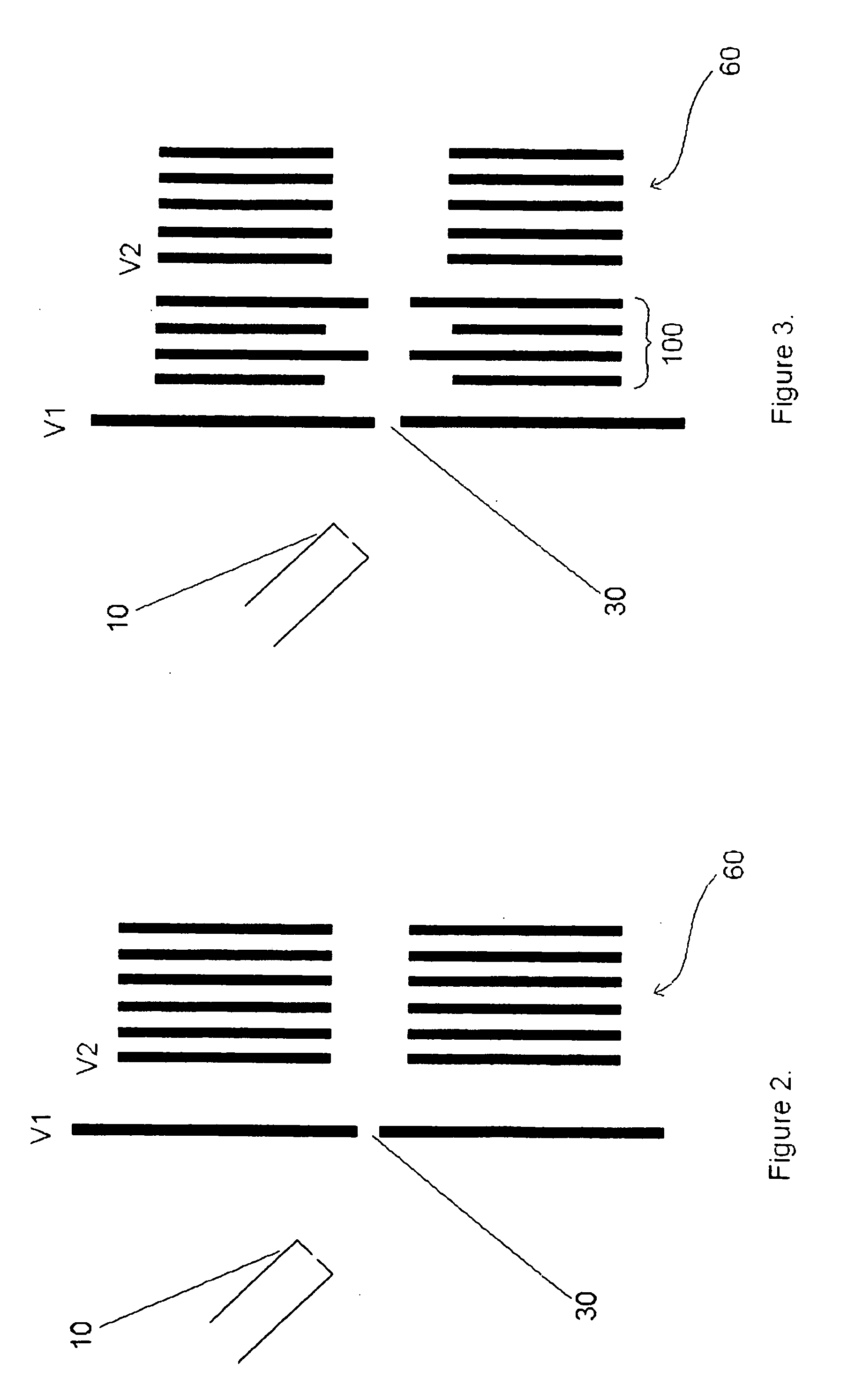
[0035]FIG. 1 shows an ion transfer arrangement embodying various aspects of the present invention, for carrying ions between an atmospheric pressure ion source (e.g. electrospray) and the high vacuum of a subsequent vacuum chamber in which one or more stages of mass spectrometry are situated. In FIG. 1, an ion source 10 such as (but not limited to) an electrospray source, atmospheric pressure chemical ionization (APCI) or atmospheric pressure photoionization (APPI) source is situated at atmospheric pressure. This produces ions in well known manner, and the ions enter an ion transfer arrangement (indicated generally at reference numeral 20) via entrance aperture 30. Ions then pass through a first pumped transport chamber 40 (hereinafter referred to as an expansion chamber 40) and on into a second vacuum chamber 50 containing an ion conduit 60. Ions exit the conduit 60 and pass through an exit aperture 70 of the ion transfer arrangement where they enter (via a series of ion lenses—not...


PUM


Abstract

An ion transfer arrangement for transporting ions between higher and lower pressure regions of the mass spectrometer comprises an ion transfer conduit 60. The conduit 60 has an inlet opening towards a relatively high pressure chamber 40 and an outlet 70 opening towards a relatively low pressure chamber. The conduit 60 also has at least one side wall surrounding an ion transfer channel 115. The side wall includes a plurality of apertures 140 formed in the longitudinal direction of the side wall so as to permit a flow of gas from within the ion transfer channel 115 to a lower pressure region outside of the side wall of the conduit 60.

Description

FIELD OF THE INVENTION[0001]This invention relates to an ion transfer arrangement, for transporting ions within a mass spectrometer, and more particularly to an ion transfer arrangement for transporting ions from an atmospheric pressure ionisation source to the high vacuum of a mass spectrometer vacuum chamber.BACKGROUND OF THE INVENTION[0002]Ion transfer tubes, also known as capillaries, are well known in the mass spectrometry art for the transport of ions between an ionization chamber maintained at or near atmospheric pressure and a second chamber maintained at reduced pressure. Generally described, an ion transfer channel typically takes the form of an elongated narrow tube (capillary) having an inlet end open to the ionization chamber and an outlet end open to the second chamber. Ions, together with charged and uncharged particles (e.g., partially desolvated droplets from an electrospray or APCI probe, or Ions and neutrals and Substrate / Matrix from a Laser Desorption or MALDI so...

Claims


Application Information

Patent Timeline
Patent Type & Authority Applications(United States)
IPC IPC(8): H01J49/04
CPCH01J49/062H01J3/14H01J49/06
Inventor MAKAROV, ALEXANDERPESCH, REINHOLDMALEK, ROBERTKOZLOVSKIY, VIACHESTAV
Owner THERMO FISHER SCI BREMEN
Why Eureka
Try Eureka