Microelectromechanical system diaphragm and fabricating method thereof

a technology of microelectromechanical system and diaphragm, which is applied in the direction of transducer diaphragms, television systems, instruments, etc., can solve the problems of high demand for mems diaphragm, easy damage of polymer thin film, and influence on the device, so as to reduce residual stress and enhance reliability and sensitivity of the upper electrode

Active Publication Date: 2010-02-25
UNITED MICROELECTRONICS CORP
View PDF9 Cites 16 Cited by
  • Summary
  • Abstract
  • Description
  • Claims
  • Application Information

AI Technical Summary

Benefits of technology

[0009]Accordingly, the present invention is directed to an MEMS diaphragm capable of reducing a residual stress in an upper electrode and enhancing a reliability and sensitivity of the upper electrode.
[0010]The present invention is further directed to a method of fabricating an MEMS diaphragm capable of reducing fabricating steps of the MEMS diaphragm.
[0019]In the present invention, the conductive layer having larger area is used as the upper electrode, and the trenches are formed in the upper electrode, such that the upper electrode has sufficient reliability, and the residual stress in the upper electrode may also be reduced, so as to solve the problem that the upper electrode is easily warped. Furthermore, the upper electrode of the present invention is a conductive layer having larger area, such that in the pressure sensing and the acoustic wave sensing process, the area of the force bearing surface of the upper electrode is increased, and the sensitivity is improved. In addition, the upper electrode of the present invention is the conductive layer having larger area, so the polymer thin film does not need to be formed on the upper electrode additionally, such that the fabricating steps are reduced.

Problems solved by technology

Moreover, along with the gradual maturity of the hearing aids technique, the demands for MEMS diaphragms grow sharply.
However, after the dielectric layer between the upper electrode and the lower electrode is removed, the metal material has larger residual stress, so the upper electrode is easily warped, which causes the influences on the device.
However, the polymer thin film does not have the characteristic of high temperature resistance, so the polymer thin film may be easily damaged in the subsequent high temperature process.
In addition, although the method may solve the problem that the upper electrode is easily warped, the reliability of the upper electrode is reduced, and the fabricating steps are increased.

Method used


Image

  • Microelectromechanical system diaphragm and fabricating method thereof
  • Microelectromechanical system diaphragm and fabricating method thereof
  • Microelectromechanical system diaphragm and fabricating method thereof

Examples


Embodiment Construction

[0027]Reference will now be made in detail to the present embodiments of the invention, examples of which are illustrated in the accompanying drawings. Wherever possible, the same reference numbers are used in the drawings and the description to refer to the same or like parts.

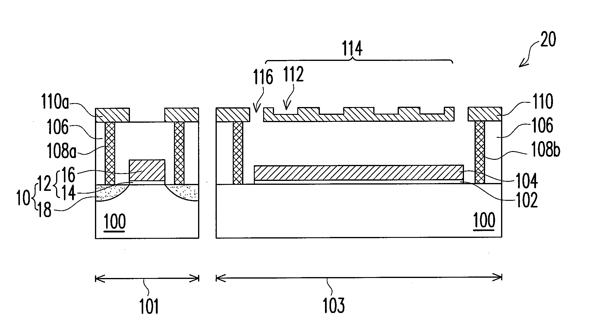
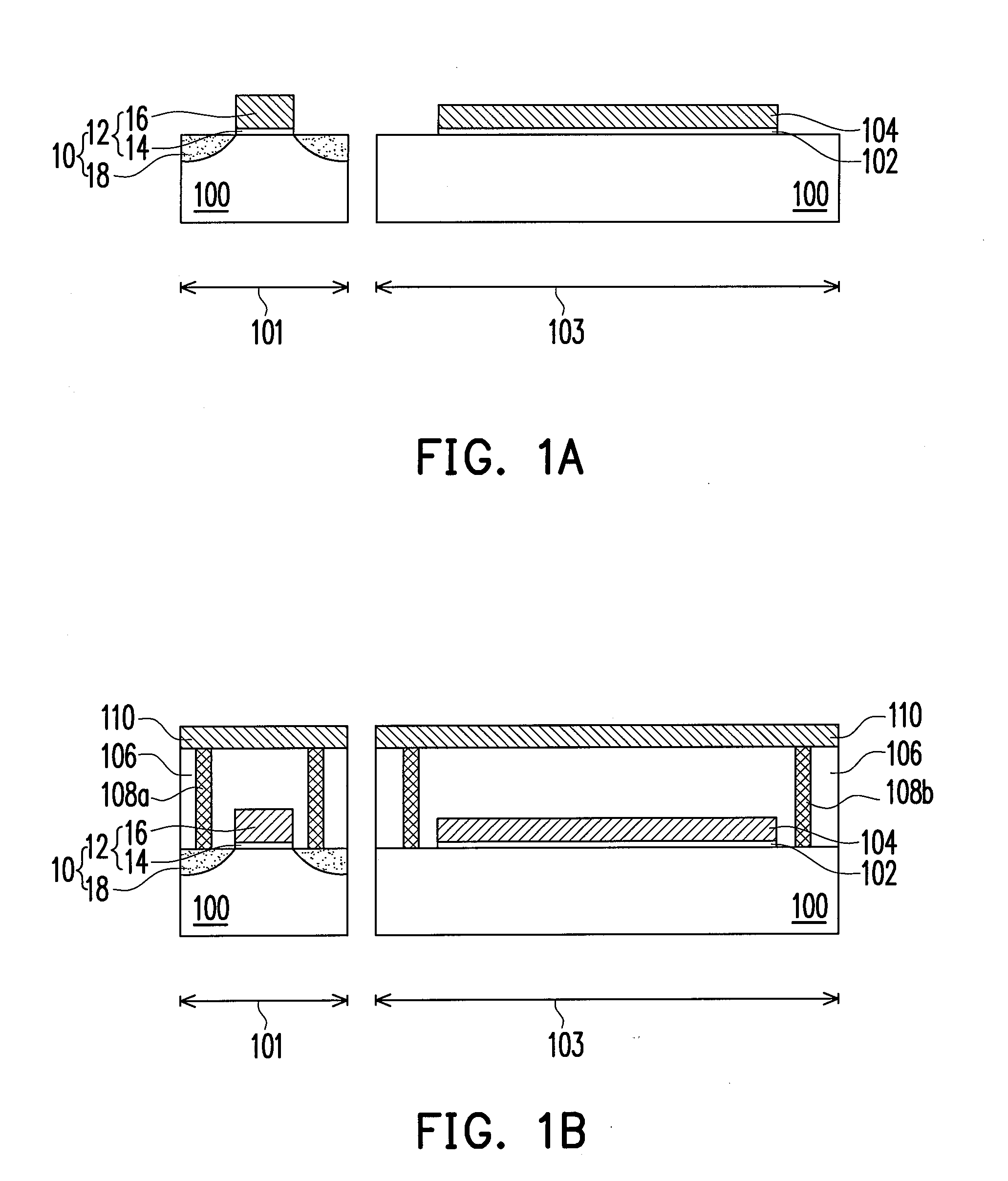
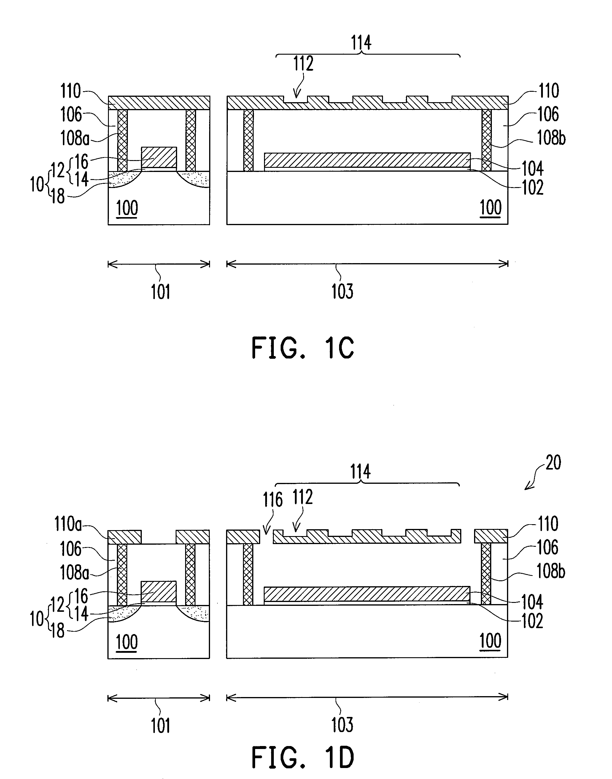
[0028]The processes for fabricating an MEMS diaphragm of the present invention may be integrated with the process of the complementary metal oxide semiconductor transistor and the process of interconnection. Therefore, in the following embodiments, the processes for fabricating the metal oxide semiconductor transistor, the interconnection, and the MEMS diaphragm are used to illustrate the present invention at the same time.

[0029]FIGS. 1A to 1D are cross-sectional views illustrating processes for fabricating an MEMS diaphragm according to an embodiment of the present invention. First, referring to FIG. 1A, a substrate 100 is provided. The substrate 100 is, for example, a silicon substrate and has regions 101 an...


PUM

PropertyMeasurementUnit
flexibleaaaaaaaaaa
conductiveaaaaaaaaaa
dielectricaaaaaaaaaa

Abstract

A microelectromechanical system diaphragm is provided. The microelectromechanical system diaphragm includes a substrate, a first conductive layer, a second conductive layer, a first dielectric layer, and a second dielectric layer. The first conductive layer is disposed on the substrate. The first conductive layer has a flexible portion in which a plurality of trenches is formed. The second conductive layer is disposed between the first conductive layer and the substrate, in which the flexible portion is located above the second conductive layer. The first dielectric layer is disposed between the second conductive layer and the substrate. The second dielectric layer is disposed between the substrate and a portion of the first conductive layer so as to suspend the flexible portion. Furthermore, at least one first opening is formed in the first conductive layer.

Description

BACKGROUND OF THE INVENTION[0001]1. Field of the Invention[0002]The present invention generally relates to a microelectromechanical system (MEMS) diaphragm and a fabricating method thereof, in particular, to an MEMS system diaphragm and a fabricating method thereof capable of reducing a residual stress in an upper electrode, enhancing a reliability and sensitivity of the upper electrode, and reducing fabricating steps.[0003]2. Description of Related Art[0004]Along with the progress of technology, various MEMS devices are fabricated by using a micro-machining technique. For example, the MEMS devices include motors, pumps, valves, switches, sensors, pixels, and diaphragms etc.[0005]The diaphragms manufactured by using the MEMS technique have advantages of light weight, small volume, and good signal quality etc, so the MEMS diaphragms increasingly become the mainstream products of the mini diaphragm. Furthermore, due to the growing demands for the mobile phones, the requirements on the...

Claims


Application Information

Patent Timeline
Patent Type & Authority Applications(United States)
IPC IPC(8): H04R7/14B81C1/00B81B7/02
CPCB81B3/0072H04R19/005B81B2203/04B81B2201/0257
Inventor WANG, MING-I
Owner UNITED MICROELECTRONICS CORP
Why Eureka
Try Eureka