Methods for reducing engine exhaust emissions
- Summary
- Abstract
- Description
- Claims
- Application Information
AI Technical Summary
Benefits of technology
Problems solved by technology
Method used
Image
Examples
Embodiment Construction
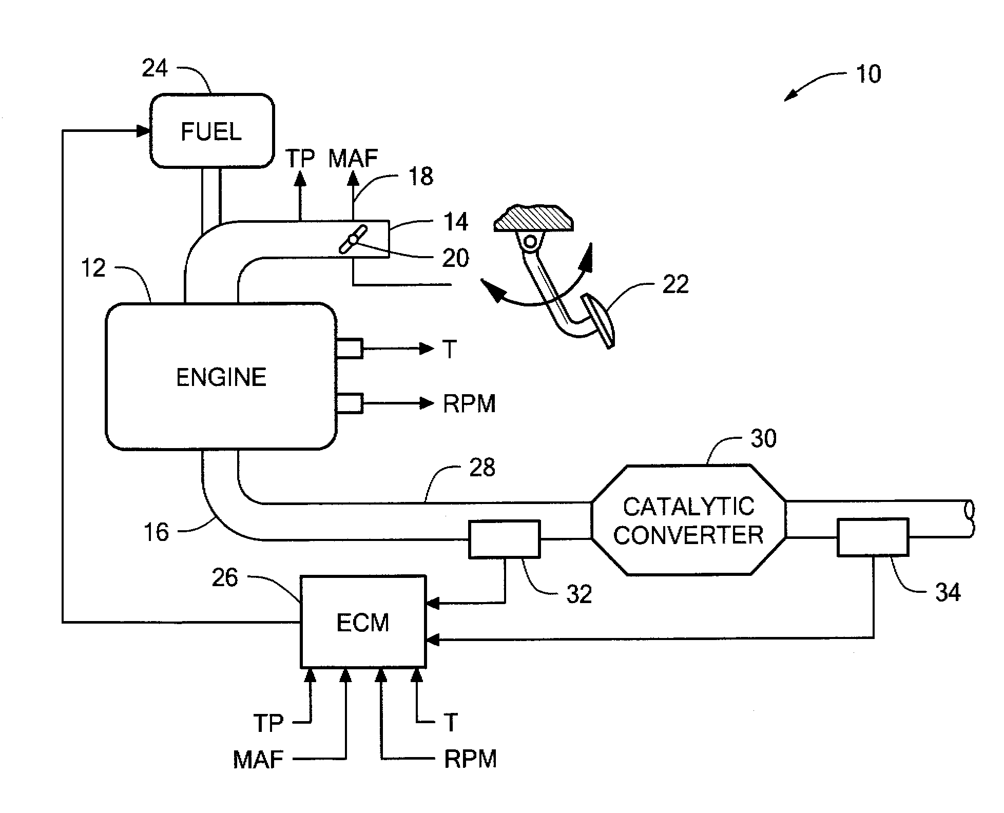
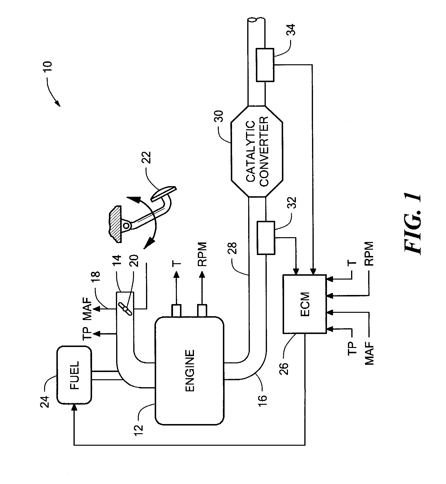
[0020]Referring now to FIG. 1, a block diagram of an engine system 10 is shown. System 10 includes an internal combustion engine 12 having an intake manifold 14 and exhaust manifold 16. Airflow through intake manifold 14 is measured by mass air flow (MAF) sensor 18 and regulated by throttle valve 20. A throttle position sensor (TPS) provides a signal indicative of position of throttle valve 20 or an associated accelerator pedal 22. A conventional fuel supply 24 provides fuel which is mixed with the air in intake manifold 14 to provide a combustion mixture which is controlled by an engine controller, such as Engine Control Module (ECM) 26. Of course, ECM 26 may perform control and monitoring functions for various vehicle systems and subsystems in addition to controlling and monitoring engine 12.
[0021]An exhaust pipe 28 couples catalytic converter 30, for example a three-way converter (TWC) to the exhaust stream of engine 12. Catalytic converter 30 is monitored via an upstream exhaust...
PUM
 Abstract
Description
Claims
Application Information
 - R&D
- Intellectual Property
- Life Sciences
- Materials
- Tech Scout
- Unparalleled Data Quality
- Higher Quality Content
- 60% Fewer Hallucinations
Browse by: Latest US Patents, China's latest patents, Technical Efficacy Thesaurus, Application Domain, Technology Topic, Popular Technical Reports.
© 2025 PatSnap. All rights reserved.Legal|Privacy policy|Modern Slavery Act Transparency Statement|Sitemap|About US| Contact US: help@patsnap.com


