
High voltage bushing

a high-voltage bushing and bushing technology, which is applied in the direction of insulated conductors, cables, conductors, etc., can solve the problems of high heat dissipation, need adequate cooling, and increase and achieves improved efficiency of the conductor with respect to cooling. , the effect of increasing the cooling performance of the conductor

Inactive Publication Date: 2010-03-04
ABB RES LTD
View PDF6 Cites 9 Cited by
  • Summary
  • Abstract
  • Description
  • Claims
  • Application Information

AI Technical Summary

Benefits of technology

[0015]In accordance with an embodiment of the invention, the electrical conductor of the high voltage bushing is coated with a surface layer which has a thermal emissivity which is preferably at least 3 times larger than the thermal emissivity of the conductor, more preferably at least 5 times larger than the thermal emissivity of the conductor and most preferably at least 7 times larger than the thermal emissivity of the conductor. An advantage of the invention is that such a layer could be made thin and will substantially increase the thermal emissivity of the conductor while still not alter any dimensional demands of the bushing. An example of such a conductor is an aluminium conductor where the emissivity of “commercial sheet” material is ca. 0.09. By enhancing the oxidation of the surface an emissivity of ca. 0.3 may be reached. A size and cost-efficient solution is thereby provided.
[0016]In accordance with another embodiment of the invention, the electrical conductor made of aluminium is anodized to the surprising effect of substantially increasing the cooling performance of the conductor. The emissivity of the anodized conductor is approximately 0.8. For a bushing conductor made of aluminium this embodiment is advantageous since it is easily facilitated, with commercially available and simple means, and the efficiency of the conductor with respect to cooling is substantially improved.
[0017]In accordance with another embodiment of the invention, the electrical conductor is coated with a surface layer substantially comprising an oxide. Examples of such oxides are copper oxide, chromium oxide and nickel oxide. An advantage of such a surface layer is that a very high emissivity can be reached. According to Handbook of Chemistry and Physics, 1971-72, 52nd Edition, Published by the Chemical Rubber Co, the emissivity of, for example, nickel oxide is 0.85-0.96 which is close to 10 times the emissivity of “commercial sheet” aluminium.
[0018]In accordance with another embodiment of the invention, the electrical conductor is coated with a surface layer substantially comprising a metal. Examples of such metals are titanium, manganese and erbium. An advantage of such a surface layer is that the layer can be made very thin. According to Handbook of Chemistry and Physics, 1971-72, 52nd Edition, Published by the Chemical Rubber Co the emissivity of, for example, titanium is 0.63 which is 7 times the emissivity of “commercial sheet” aluminium.
[0019]In accordance with another embodiment of the invention, the electrical conductor is coated with a surface layer substantially comprising an aluminium oxide. An advantage of aluminium oxide is that it is inherently compatible with aluminium which is very often used as a conductor material. Another advantage is that it is very inert and intoxic.
[0020]In accordance with another embodiment of the invention, the electrical conductor is coated with a surface layer substantially comprising of an organic or semi-organic substance. Examples of such substances are acrylic polymer paints and epoxy paints. An advantage with such layer materials is that they are very easy to apply using a brush or with a spraying device. Another advantage is that the layer is inexpensive since both the material and the application method are low cost.

Problems solved by technology

Electrical equipment and devices, and in particular high voltage equipment in an electrical power distribution system, have high heat dissipation and therefore require adequate cooling.
However, there are also electrical devices within a power distribution system that are not cooled by any external cooling system.
Naturally, such high voltages and current levels result in still higher heat dissipation.
This temperature difference causes thermal stresses to the outer insulator housing, in the longitudinal direction of the bushing.
This will cause circumferential thermal stresses to the outer insulator housing of the bushing.

Method used


Image

  • High voltage bushing
  • High voltage bushing

Examples


Embodiment Construction

[0026]When applicable the same reference numerals are used throughout the description for denoting same or similar parts.

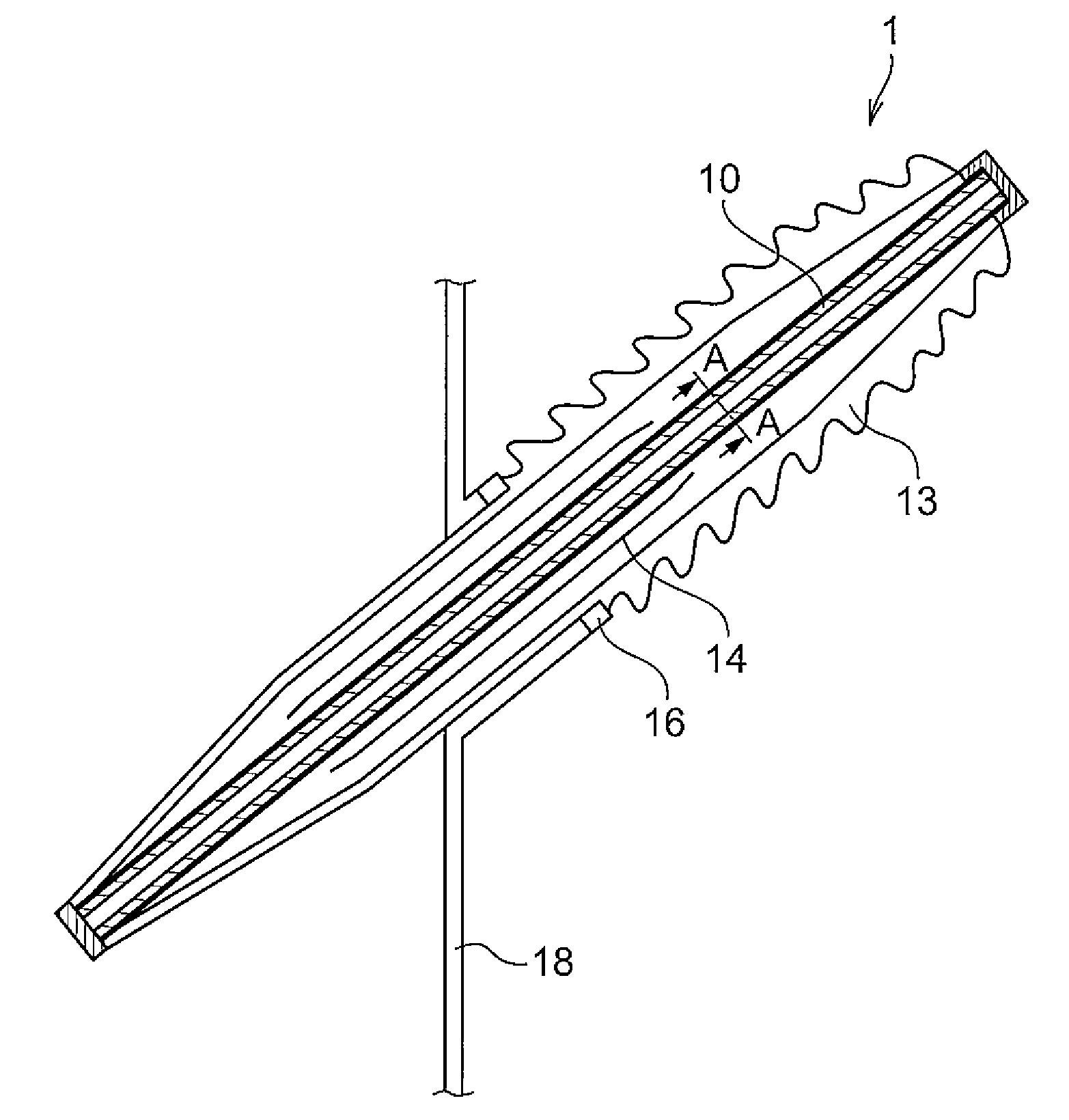
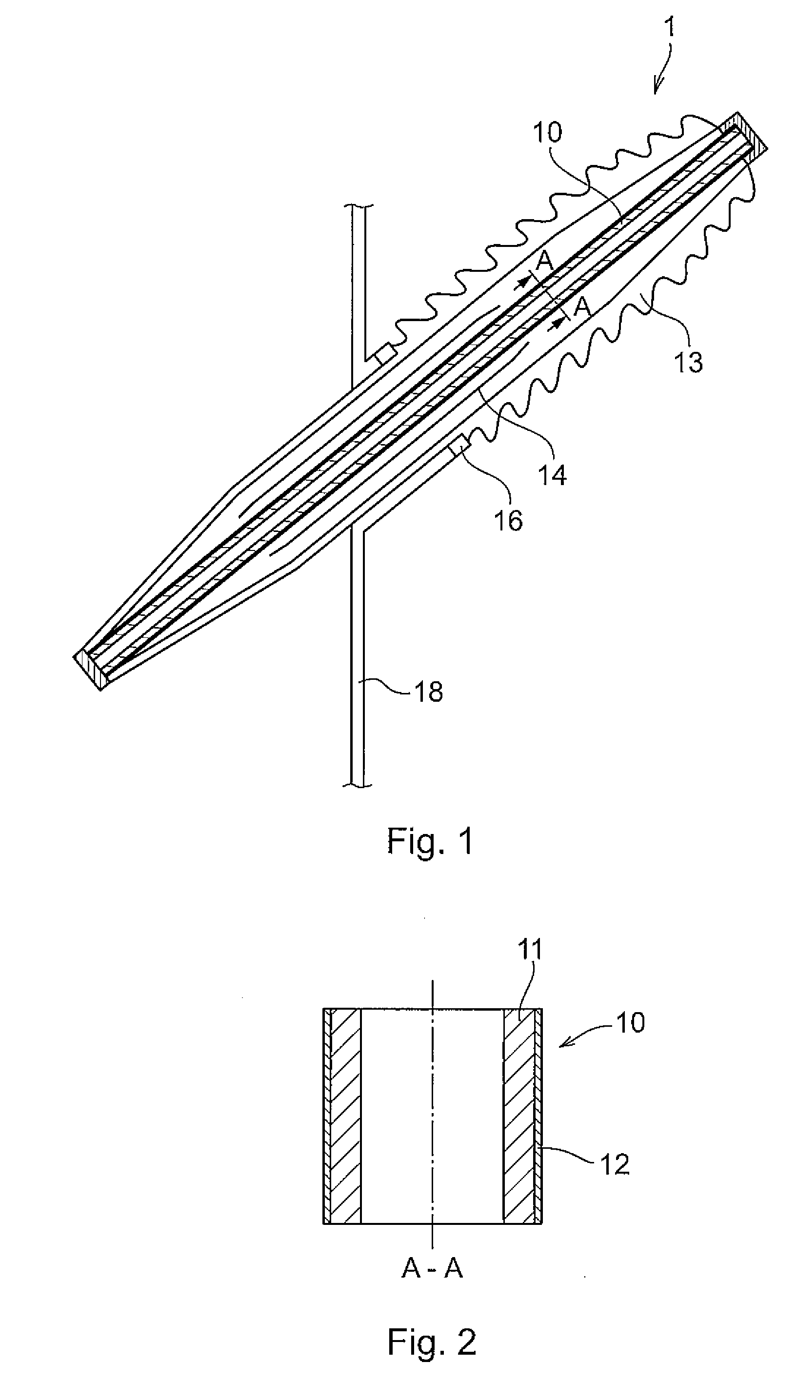
[0027]A bushing according to an embodiment of the invention is shown in FIG. 1. The bushing comprises a high voltage conductor unit 10. In FIG. 2, a cross-sectional view of the high voltage conductor unit 10 of the bushing 1 of FIG. 1 is shown. The voltage conductor unit 10 comprises an electrical conductor 11 and an emissive surface layer 12 of a material having a thermal emissivity substantially larger than the thermal emissivity of the conductor 11. The high voltage conductor unit 10 runs through the centre of a hollow bushing insulator 13, which forms a housing around the high voltage conductor unit 10. Typically, for an open air application the insulator housing 13 is made of either porcelain or a polymeric material such as epoxy with the outer side comprising silicone sheds.

[0028]In a reflector bushing, a rotationally symmetrical reflector 14 is provided, wi...


PUM


Abstract

A high voltage bushing for transferring AC or DC high voltage and current. The bushing includes an electrically connectable electrical conductor, an insulator housing enclosing the conductor, and a space filled with an electrically insulating gas in between said insulator housing and said conductor. The electrical conductor is coated with a surface layer of a material having a thermal emissivity substantially larger than a thermal emissivity of the conductor.

Description

FIELD OF THE INVENTION[0001]The present invention relates to the field of electrical power distribution systems and in particular to cooling of high voltage bushings in such power distribution systems.BACKGROUND OF THE INVENTION[0002]Electrical equipment and devices, and in particular high voltage equipment in an electrical power distribution system, have high heat dissipation and therefore require adequate cooling. For example, a conventional HVDC (High-Voltage Direct Current) converter valve may be air insulated and water-cooled. A cooling system is conventionally provided comprising for example cooling water distribution pipes that are shaped to fulfil certain requirements. Another example of an external cooling system is the use of fans.[0003]However, there are also electrical devices within a power distribution system that are not cooled by any external cooling system. Those devices, lacking an external cooling system, are then instead just self-cooled, i.e. natural convective ...

Claims


Application Information

Patent Timeline
IPC IPC(8): H01B17/54
CPCH01B7/428H01B17/54H01B17/28
Inventor TORNKVIST, CHRISTERWIDLUND, OLA
Owner ABB RES LTD
Learn More