Electric device

a technology of electric devices and driving motors, applied in the field of electric vehicles, can solve the problems of high cost, unviability of commercial production, and high pressure on the immobilized oxygen supply and hydrogen storage technology, and achieve the effects of reducing the load amount of the driving motor, improving the working condition and the use life of the driving motor and the storage battery

Inactive Publication Date: 2010-03-04
FENGRI ELECTRIC GROUP CO LTD
View PDF0 Cites 3 Cited by
  • Summary
  • Abstract
  • Description
  • Claims
  • Application Information

AI Technical Summary

Benefits of technology

[0030]3. Due to the energy accumulator engaged with the small drive gear on the output end of the transmission located on the driving device in the invention, external mechanical energy for the driving device is provided when starting to impel the transmission to drive the wheel. Thus, the loading amount of the driving motor can be decreased, and the working condition and the usage life of the driving motor and storage battery can be improved.
[0031]4. Due to the electric driving device comprising the second gear transmission and the high-low torque converter whose inputs are connected with a small drive electric machine and a big drive electric machine respectively, the matching problem of the working condition and the motor power is solved, and furthermore, higher energy conversion can be obtained. That is, the vehicles are driven by the big drive electric machine when starting and are driven by the small drive electric machine when accelerating, in order to satisfy the different working conditions in starting and accelerating. The working conditions of the motor and the storage battery are improved, and the life of the driving electric machine and storage battery can be prolonged. The torque force and drive performance when accelerating, ascending hills, and high-speed driving is improved especially in assistance of the energy accumulator. Thus, the vehicles are able to work with optimum efficiency. The transmission loss can be reduced, while the continuous driving mileage and the loading of the electric vehicles can be improved.
[0032]5. Due to the pole rods of the storage battery connected and screw jointed by screw threads with the male and female joints matched with the end of the said conducting wire in the present invention, connection resistance of the storage battery can be decreased so the energy consumption can be reduced. Furthermore, it is convenient to assemble and disassemble the structure.
[0033]6. Due to the device for driving the air conditioning compressor and the wiper using compressed gas stored in the interlayer, electric energy can be saved so as to increase the continuous driving mileage.
[0034]7. Due to the energy accumulator comprised of several energy storage units with novel structure and light weight, the energy storage, the torque, and the usage life can be increased, and the electric energy consumption can be reduced to increase the continuous driving mileage.
[0035]In conclusion, the present invention provides an electric vehicle which can improve the working condition of the vehicles and reduce energy consumption. When driving, the vehicles can obtain energy in several ways to increase the continuous driving mileage of the vehicles and prolong the life of the storage battery and driving motor. The higher energy conversion efficiency makes the vehicle fit for mass production to be the upgraded product of current electric vehicles.

Problems solved by technology

However, immature hydrogen fuel energy conversion technology, immature oxygen supply and hydrogen storage technology in high pressure, high cost, and the unviability of commercial production constitute the shortcomings of fuel cell electric vehicles.
However, the disadvantages are a complicated dynamic system, high cost, too much space needed, and environmental pollution, despite the reduced noise and emission of hazardous substances, which result in a secondary combustion conversion defect.
However, its short continuous driving mileage, low maximum driving velocity, long charging time, great transmission loss, and high cost are the principal drawbacks of the full-electric vehicle.
The reasons for said short continuous driving mileage of electric vehicles and the short life of the storage battery are the abundant weight of the whole vehicle, great transmission loss, the single energy supplementation method, small charging speed, and especially the conventional actuation method, causing low energy conversion efficiency.
In addition, large connection resistance, the inconvenience of replacing batteries, and great driving energy consumption of the air conditioning system and wiper due to unreasonable battery connection structure cause other reasons for the undesirable performance of electric vehicles.
So far, the research effect is not satisfying in spite of the development resulting from continued efforts in the field.

Method used


Image

  • Electric device
  • Electric device
  • Electric device

Examples


Embodiment Construction

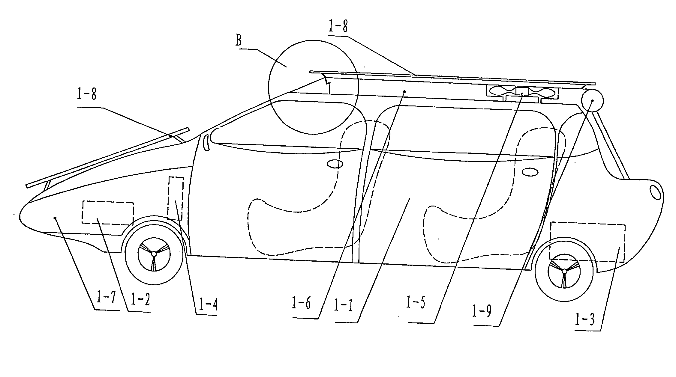
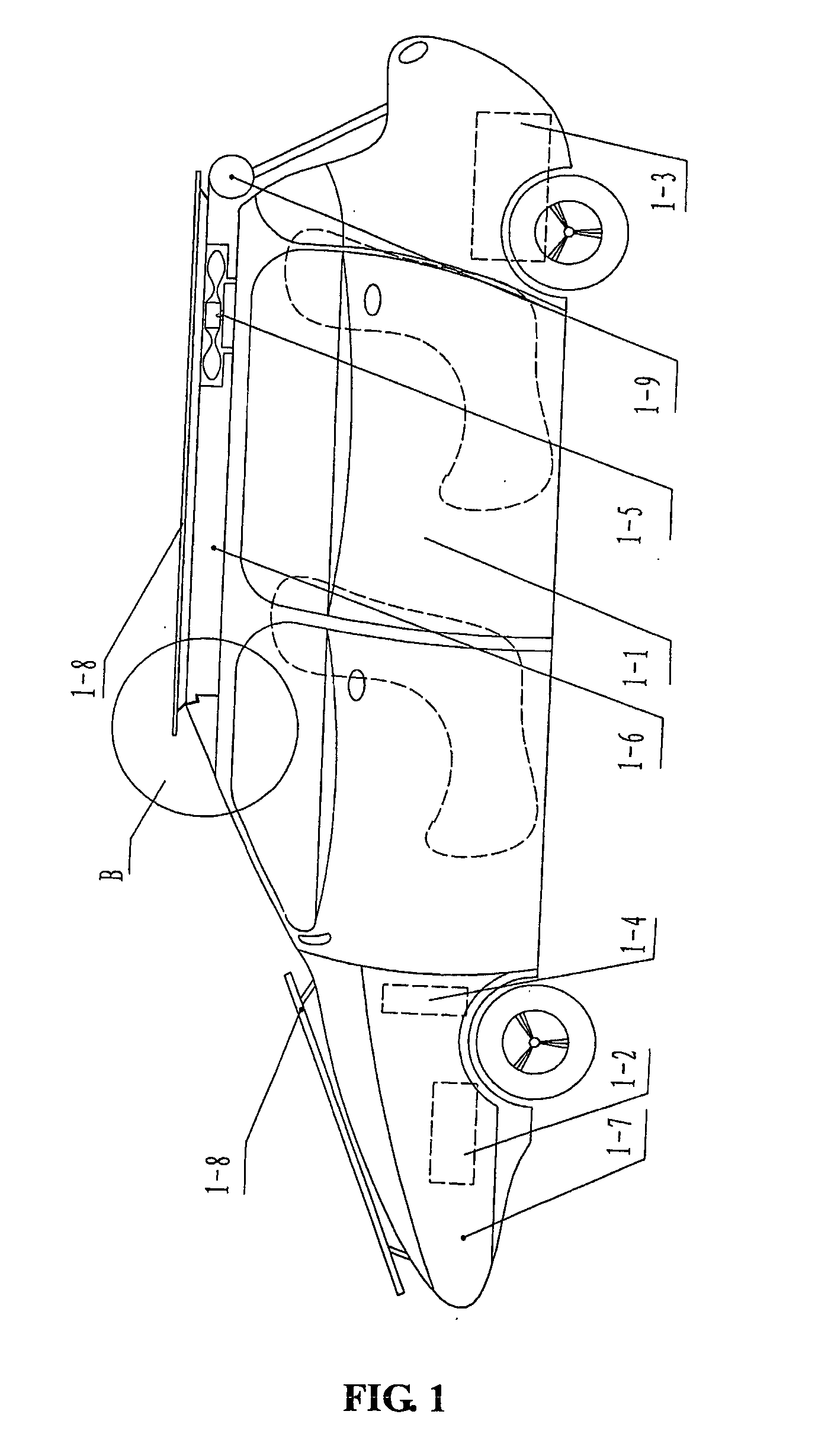
[0047]Referring to FIG. 1, an electric vehicle in the present invention comprises a body 1-1, an electric driving device 1-2, a storage battery 1-3, and a control system 1-4, wherein the said body 1-1 is provided with a wind electric power generation device 1-5, and several solar panels 1-8 are provided on the top 1-6 of the body 1-1 and the hood 1-7, and the said solar panel 1-8 is electrically connected to the storage battery 1-3.

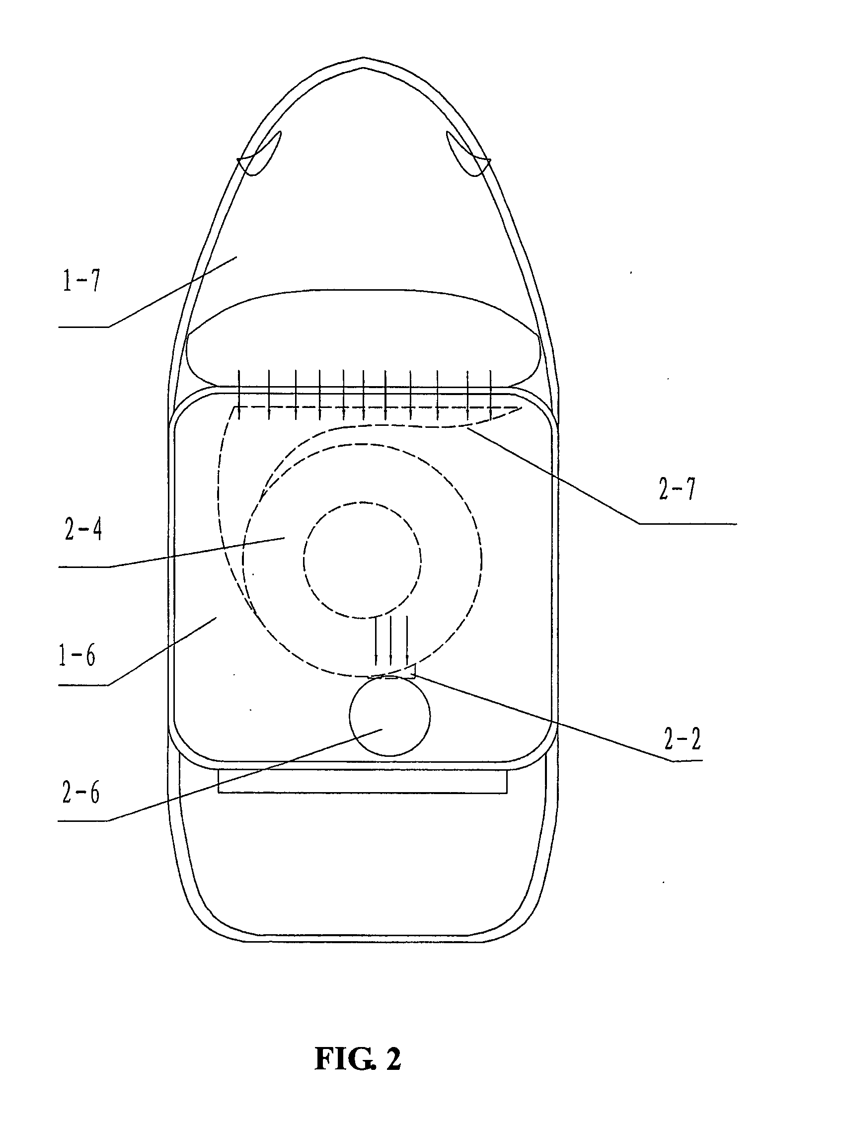
[0048]Referring to FIG. 1, FIG. 2, FIG. 3, and FIG. 4, the said wind electric power generation device 1-5 comprises wind scoop 2-4, an impeller chamber 2-6, an impeller chamber cover 3-9, a blade 3-8, a rotor 3-7, a driving shaft 3-5, a shaft sleeve 3-6, a release bearing 3-4, a shifting fork 3-3, a gear box 3-2, and an electric power generator 3-1. Wherein the said wind scoop 2-4 integrated with the body 1-1 which can open and close the air inlet 2-7 is installed on the top 1-6 of the body 1-1. At the end of the wind scoop 2-4 there is a wind fairing 2-2...


PUM


Abstract

An electric vehicle comprises a body (1-1), an electric driving device (1-2), a storage battery (1-3) and a control system (1-4), wherein the said body is provided with a wind electric power generation device (1-5), several solar panels (1-8) are provided on the top (1-6) of the body and the hood (1-7), the said solar panel (1-8) is electrically connected to the storage battery

Description

TECHNICAL FIELD[0001]The present invention relates to a vehicle, especially to an electric vehicle.BACKGROUND ART[0002]Present domestic and foreign automobiles can be divided into the following three categories: fuel cell electric vehicles, hybrid power vehicles, and full-electric vehicles. The fuel cell electric vehicle is fueled with hydrogen and driven by the power source produced by the chemical reaction between hydrogen and oxygen. Its virtue is its high energy conversion efficiency, which is several times more than that of an internal combustion engine. In addition, the fuel cell electric vehicle, with its compact structure and fewer components possesses the advantages of rich resources and environmental protection due to its pollution-free reaction products like water. However, immature hydrogen fuel energy conversion technology, immature oxygen supply and hydrogen storage technology in high pressure, high cost, and the unviability of commercial production constitute the shor...

Claims


Application Information

Patent Timeline
Patent Type & Authority Applications(United States)
IPC IPC(8): B60L8/00B60K25/00B60L11/18B60K11/00
CPCB60K16/00B60K2016/006B60L8/00B60L8/003Y02E10/725F03D9/002F05B2240/941Y02T10/7083Y02T10/90B60W2510/244F03D9/25Y02E10/50Y02E10/728Y02E10/72Y02P70/50Y02T10/7072Y02E70/30F03D9/007F03D3/04H02S10/12F03D15/00F03D9/12F03D9/32
Inventor LI, FU GENZHANG, SHENGLIANG
Owner FENGRI ELECTRIC GROUP CO LTD
Why Eureka
Try Eureka