Phase contrast imaging

a phase contrast and xray image technology, applied in the direction of material analysis, instruments, applications, etc., can solve the problem of uncollimated radiation, and achieve the effect of improving sensitivity or reducing deflection

Active Publication Date: 2010-03-04
UCL BUSINESS PLC
View PDF8 Cites 19 Cited by
  • Summary
  • Abstract
  • Description
  • Claims
  • Application Information

AI Technical Summary

Benefits of technology

[0053]When X-rays are emitted from the x-ray source 2 in the absence of a sample, the x-rays are transmitted in the beam direction and are absorbed by solid regions of the sample mask 8. Where the x-rays hit the apertures 32 in the sample mask they are transmitted as discrete beams 16 which fall on the detector mask 6. Each discrete beam 16 is arranged to fall partially on the x-ray absorbing region 18 and partially on the uncovered area 22 of the corresponding pixel 12, i.e. the discrete beam covers the edge 20. This means that only a certain fraction of the X-rays of each discrete beam 16 reach the uncovered area 22 of the pixel 12 and hence are measured.
[0054]Note that because of the divergent nature of the X-rays the pitch of apertures 32 in the sample mask 8 is smaller than the pitch of apertures 30 in detector mask 6.
[0055]In use, as shown in FIG. 2, a sample 14 is placed in the sample region 10 and the discrete beams 16 are slightly deflected by angle θ a

Problems solved by technology

Such commercial sources generally produce much less radiation

Method used


Image

  • Phase contrast imaging
  • Phase contrast imaging
  • Phase contrast imaging

Examples


Embodiment Construction

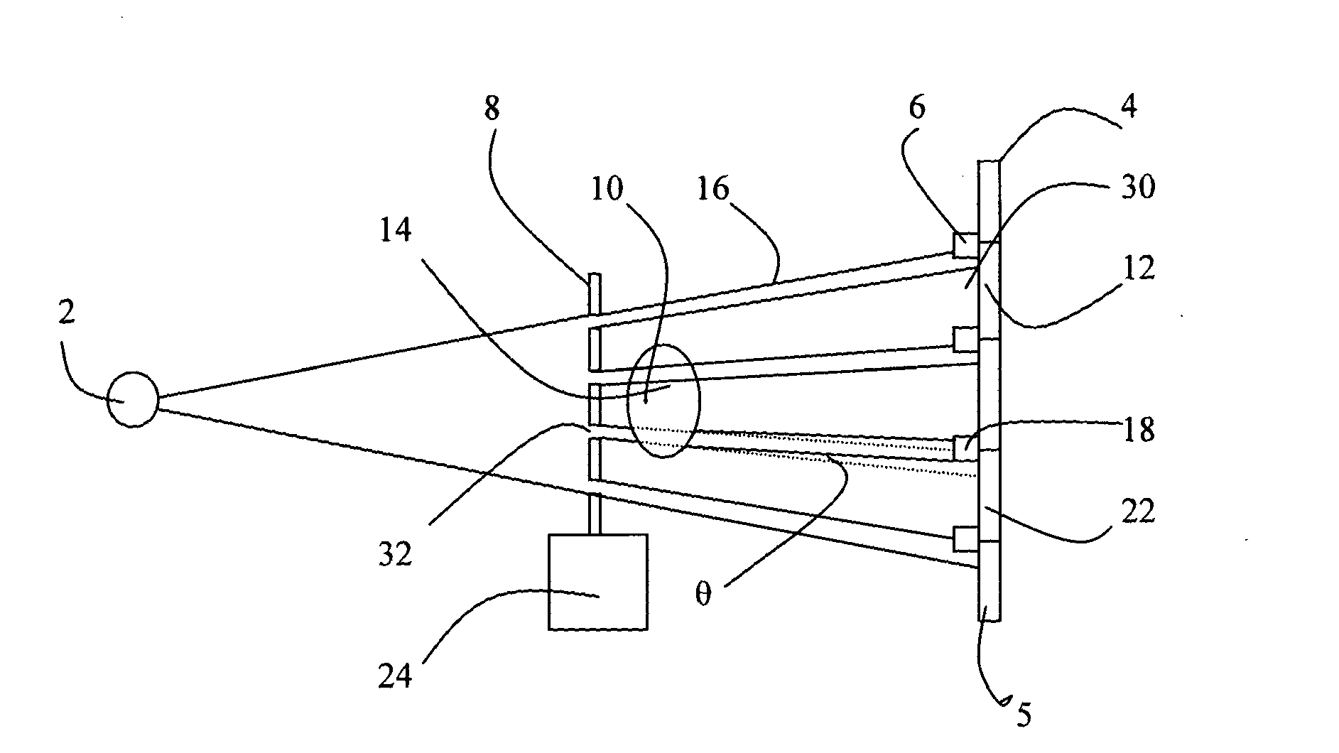
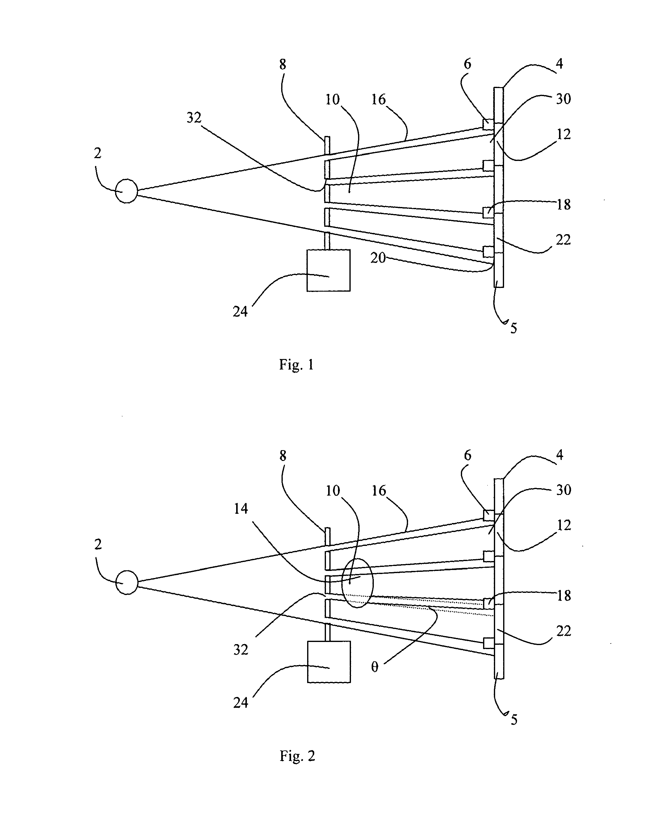
[0049]Referring to FIG. 1, the system according to the first embodiment of the invention consists of an x-ray source 2, an x-ray detector 4 and a sample mask 8 placed immediately before the sample region 10. The x-ray source is not a synchrotron source, which would be inherently collimated and monochromatic, instead it is a conventional commercial source. For example, the source may be a molybdenum target source; many other commercial sources are available. Such sources are not in general monochromatic, instead although such sources frequently have a dominant energy they in fact emit small amounts of energy at other frequencies, and in this sense are polychromatic. Thus, in this specification, “polychromatic” is not intended to require a broad spectrum of frequencies. Further, such commercial sources are also not inherently collimated in the way that synchrotron sources are, instead X-rays are emitted in a range of angles; thus the emitted X-rays are both divergent and uncollimated....


PUM


Abstract

Phase contrast imaging is achieved using a sample mask 8 and a detector mask (6). X-rays emitted from x-ray source (2) are formed into individual beams (16) by sample mask which pass through sample (14) and arrive at individual pixels (12) of the detector (4) through detector mask (6). The individual x-ray beams are arranged to hit the pixel edge (20) of individual rows of pixels, individual columns of pixels or individual pixels. Small deviations θ in the individual beams (16) cause a significant increase or decrease in the signal hitting the exposed area (22) of the pixel resulting in a significant phase contrast signal.

Description

FIELD OF INVENTION[0001]The invention consists in an apparatus for generating a phase contrast (PC) x-ray image and a method of generating such an image.BACKGROUND ART[0002]Phase contrast (PC) is an exciting emerging x-ray imaging technique which removes most of the limitations of conventional x-ray imaging. Phase contrast can be applied to all fields of x-ray imaging, i.e. medical (diagnosis and treatment planning / delivering / monitoring), industrial (inspections, non-destructive testing) as well as to homeland security (security inspections). Basically all these fields would strongly benefit from the introduction of a reliable PC technique, as this would result in a strongly increased visibility of all details and in the possibility of detecting features which are invisible to conventional techniques.[0003]A review of PC imaging is provided in R. Lewis, Medical phase contrast x-ray imaging: current status and future prospects, Phys. Med. Biol. volume 49 (2004) pages 3573-83.[0004]Un...

Claims


Application Information

Patent Timeline
IPC IPC(8): G21K1/06A61B6/00
CPCG01N23/04G01N23/041A61B6/00G01N23/20
Inventor OLIVO, ALESSANDROSPELLER, ROBERT D.
Owner UCL BUSINESS PLC
Why Eureka
Try Eureka