Polyimide tube, method for production thereof, method for production of polyimide varnish, and fixing belt

a technology of polyimide varnish and polyimide tube, which is applied in the direction of tubular articles, synthetic resin layered products, electrography/magnetography, etc., can solve the problems of insufficient improvement of thermal conductivity in the thickness direction, large waiting time, and small electric power consumption, so as to achieve good tensile strength and modulus of elasticity, increase the fixing speed, and high thermal conductivity

Active Publication Date: 2010-03-04
SUMITOMO ELECTRIC IND LTD +1
View PDF4 Cites 41 Cited by
  • Summary
  • Abstract
  • Description
  • Claims
  • Application Information

AI Technical Summary

Benefits of technology

[0025]The present invention can provide a polyimide tube having a high thermal conductivity, and in addition, a good tensile strength and modulus of elasticity. The polyimide tube of the present invention has the above good properties, and thus, when the polyimide tube is used as a base member of a fixing belt, a fixing belt which can realize an increase in the fixing speed, a decrease in the fixing temperature, and a significant improvement in, for example, the fixing property of a full-color toner can be obtained.
[0026]The polyimide tube of the present invention has high tensile strengths in the circumferential direction and in the axial direction and a high-level modulus of elasticity. Accordingly, when the polyimide tube is used as a base member of a fixing belt, for example, twist deformation, and cracking and flattening at an end of the belt can be suppressed. According to the fixing belt including the polyimide tube of the present invention as a base member, cracking or breaking does not readily occur.

Problems solved by technology

However, a fixing roller having such a structure requires a relatively long waiting time to increase the surface temperature of the fixing roller to a fixing temperature with the heating means disposed in the hollow part thereof.
In this fixing method, only a portion necessary for fixing is heated, and thus the electric power consumption is also small.
However, such a fixing belt including a polyimide tube as a base member is composed of a polyimide resin having a low thermal conductivity and a fluorocarbon resin.
However, in this endless belt, since the thermally conductive property of the endless belt made of the polyimide resin is insufficient, the improvement in the thermal conductivity in the thickness direction is not sufficient.
In addition, since the endless belt requires a step of forming the inner layer, the cost increases.
However, when the mixing ratio of the inorganic filler to the polyimide resin is too low, it is difficult to sufficiently increase the thermal conductivity of the resulting polyimide tube.
When the content of the boron nitride in the polyimide resin is too low, the thermal conductivity of the fixing belt cannot be satisfactorily increased, and thus it is difficult to achieve required performances such as an increase in the fixing speed.
In addition, when the content of the boron nitride in the polyimide resin is too low, the modulus of elasticity does not also sufficiently increase, and thus twist deformation of the fixing belt and flattening at an end of the fixing belt readily occur.
Therefore, when the tensile strength of the fixing belt is too low, breaking of the fixing belt and cracking at the edges of the belt readily occur.
These problems become serious when both the tensile strength and the modulus of elasticity in tension of the fixing belt decrease.

Method used


Image

  • Polyimide tube, method for production thereof, method for production of polyimide varnish, and fixing belt
  • Polyimide tube, method for production thereof, method for production of polyimide varnish, and fixing belt
  • Polyimide tube, method for production thereof, method for production of polyimide varnish, and fixing belt

Examples


example 1

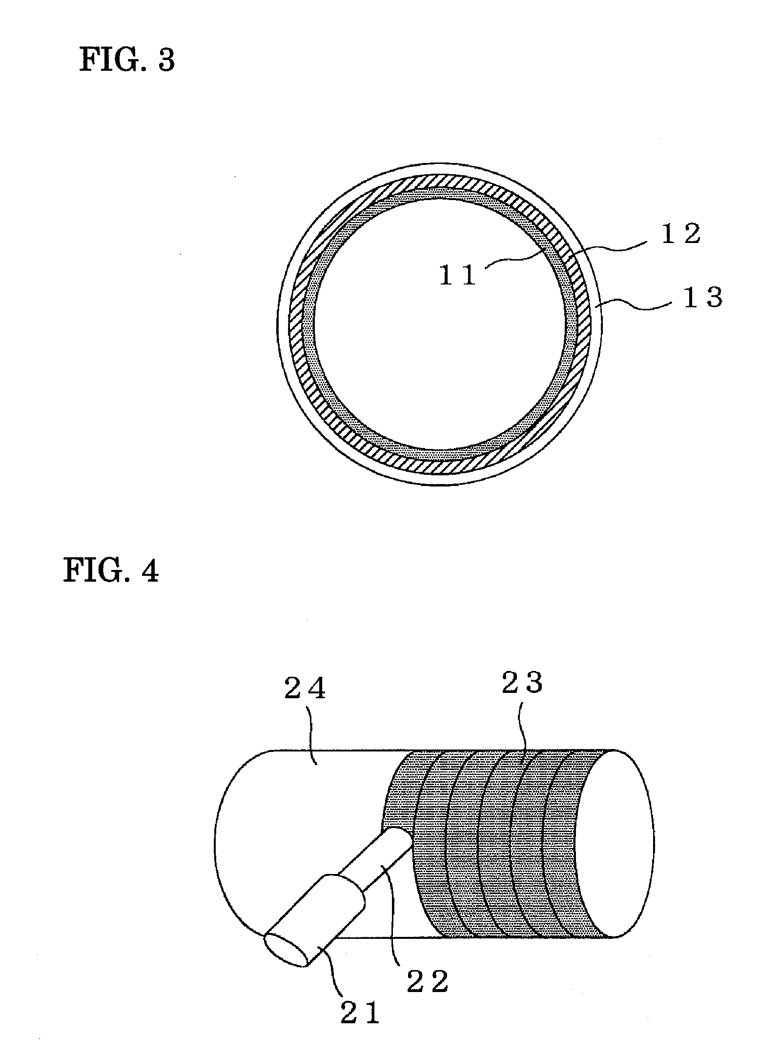
[0115]An aluminum column with an outer diameter φ of 20 mm, the outer surface of which was coated with a ceramic, was used as a core body functioning as a metal mold. A nozzle (discharge opening) attached to a supply portion of a dispenser was brought into contact with the outer surface of the core body while rotating the core body. On the basis of the total volume of the solid content, 10 volume percent of boron nitride (“MBN-010T” produced by Mitsui Chemicals, Inc., graphite structure-type BN, specific gravity: 2.27), and 5 volume percent of carbon nanotube (“VGCF” produced by Showa Denko K.K., diameter φ: 150 nm, length: 8 μm, specific gravity: 2.0) were added to a polyimide varnish used as a raw material [“U-varnish S-301” produced by Ube Industries Ltd., specific gravity: 1.446; a polyimide precursor varnish formed into a polyimide resin having a repeating unit represented by formula (A) above]. The resulting mixture was preliminarily stirred with a stirrer, and mixed with a th...

example 2

[0117]A polyimide tube was prepared as in Example 1 except that, in Example 1, the content of the boron nitride was changed to 15 volume percent and the content of the carbon nanotube was changed to 2 volume percent.

example 3

[0118]A polyimide tube was prepared as in Example 1 except that, in Example 1, the content of the boron nitride was changed to 15 volume percent and the content of the carbon nanotube was changed to 3.5 volume percent.


PUM

PropertyMeasurementUnit
diameteraaaaaaaaaa
diameteraaaaaaaaaa
viscosityaaaaaaaaaa

Abstract

A polyimide tube composed of a polyimide resin composition in which 5 to 23.5 volume percent of boron nitride and 1 to 15 volume percent of an acicular substance are dispersed as a filler in a polyimide resin on the basis of the total volume of the composition, a method of producing the tube, a method of producing a polyimide varnish used for producing the tube, and a fixing belt including the tube as a base member are provided.

Description

TECHNICAL FIELD[0001]The present invention relates to a polyimide tube, and more specifically, to a polyimide tube having a high thermal conductivity and a good tensile strength and modulus of elasticity. In addition, the present invention relates to a method of producing the polyimide tube, a polyimide varnish used for producing the polyimide tube, and a fixing belt including the polyimide tube as a belt base member.BACKGROUND ART[0002]In general, in image-forming apparatuses utilizing an electrophotographic method (including an electrostatic recording method), such as a copy machine, a facsimile, and a laser beam printer, an image-forming process includes an exposure step of performing an image exposure on a photosensitive member to form an electrostatic latent image; a development step of applying a toner (colored resin particles) to the electrostatic latent image to form a toner image; a transfer step of transferring the toner image onto a material to be transferred such as a re...

Claims


Application Information

Patent Timeline
Patent Type & Authority Applications(United States)
IPC IPC(8): B32B1/08B29C41/02C08K5/20
CPCB29C41/085Y10T428/139C08G73/1046C08G73/105C08G73/1067C08G73/1071C08G73/14C08K3/38C08K7/22C08L79/08G03G15/2053G03G2215/2035G03G2215/2048C08G73/1042Y10T428/31721G03G15/2057
Inventor NAKAJIMA, SHINGOSUGAWARA, JUNMIZOGUCHI, AKIRAONMORI, NAOKISUZUKI, YOSHIMASAKIZAWA, KAZUHIROUCHIBA, YUSUKE
Owner SUMITOMO ELECTRIC IND LTD
Why Eureka
Try Eureka