Display apparatus and cellular phone, computer and television including the same

a technology of display apparatus and cellular phone, which is applied in the field of display device and cellular phone, computer and television, can solve the problems of consuming 45% of the rated power of the computer, light source and color filter are expensive components, and the lcd lighting efficiency is usually less than 1%, so as to improve the light transmission ratio and improve the use of energy. , the effect of reducing the cos

Inactive Publication Date: 2010-03-11
SUN RUNWEN
View PDF13 Cites 34 Cited by
  • Summary
  • Abstract
  • Description
  • Claims
  • Application Information

AI Technical Summary

Benefits of technology

[0042]2. The display device of the present invention can be improved directly on basis of a current display device, and the luminescent color filter for the blue sub-pixels of the display elements can be omitted, so that the cost can be reduced and the light transmission ratio can be increased, thereby the energy can be better used.
[0043]3. In the display device according to the present invention, the light emission elements configured for monochromatic light are reduced, so that the fabrication procedure is simplified, and cost is reduced.
[0044]4. In the display device according to the present invention, the light emission elements configured for monochromatic light are same, such that the influence on display performance caused by asynchronous aging process of different color light emission elements is avoided.
[0045]5. In the display device according to the present invention, the contrast ratio of the display device is enhanced, and by means of the dynamic control for light sources, such as local brightness control and black screen insertion, the image residue is reduced, such that the contrast ratio could be further enhanced and the energy consumption could be further reduced. In addition, by the down conversion of high photon energy light of ultraviolet or cyan monochromatic or polychromatic light, a better color purity can be generated by choosing a photoluminescent material with a narrower full-width at half the maximum spectrum, resulting in a greater color display area.

Problems solved by technology

However, the LCD lighting efficiency is usually less than 1%, for example in a 15 inch notebook computer, wherein the light source consumes 45% of the rated power of the computer.
Besides, the light source and the color filter are expensive components in a LCD, and for example, account for 30% total cost of a small and mid-sized LCD or 60% of a large-scaled LCD such as for television.

Method used


Image

  • Display apparatus and cellular phone, computer and television including the same
  • Display apparatus and cellular phone, computer and television including the same
  • Display apparatus and cellular phone, computer and television including the same

Examples


embodiment 1

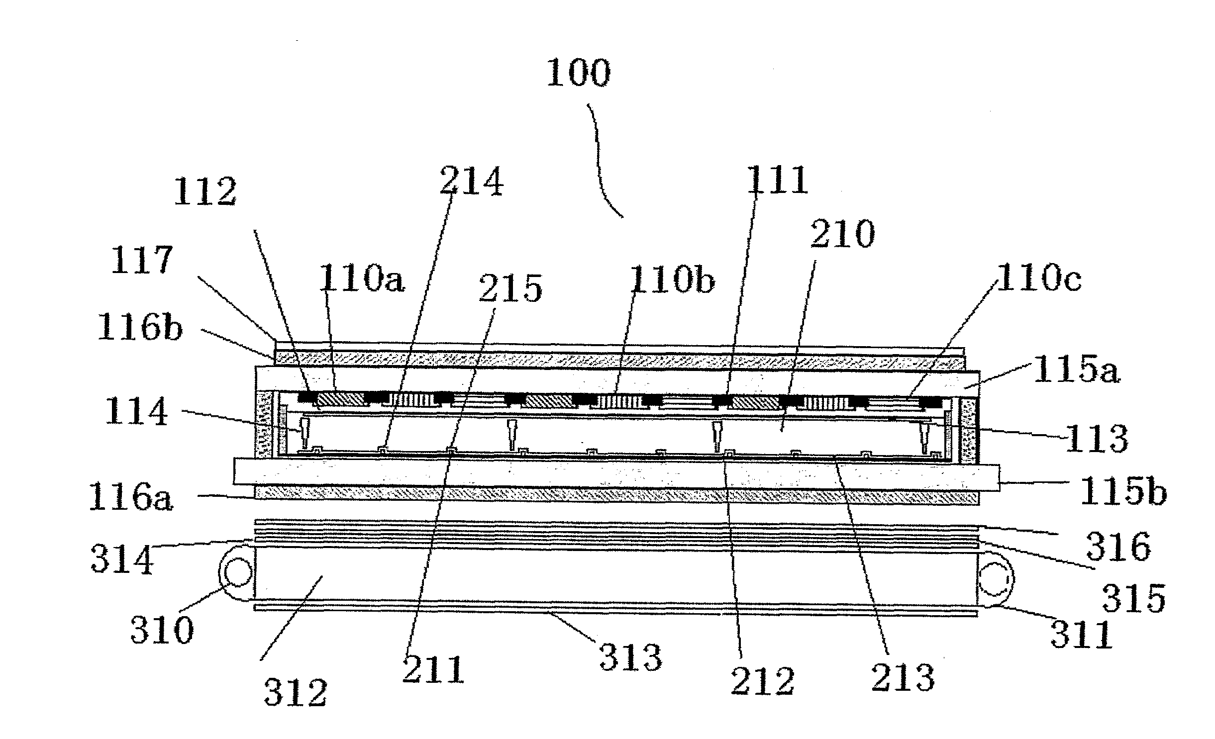
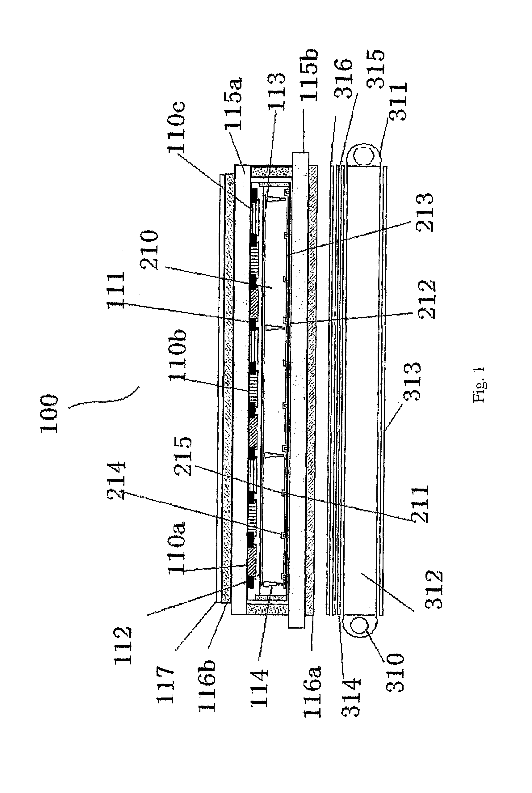
[0118]The display device of the present embodiment may have any one of the structures illustrated in FIGS. 4-6, the difference from the prior art lies in that a CCFL or GaInN blue light source 310′ is used here and a photoluminescence film 110′ is provided on the first substrate 116a.

[0119]A CCFL tube, a light source 310′, has a diameter of 1.8 mm, and is as long as the size of LCD panel.

[0120]In addition, in the embodiment shown in FIG. 4, an ultraviolet stopping film 117 is provided on the photoluminescence film 110′.

[0121]The luminescent material of green luminescent sub-pixels 110b′ is selected from coumarin (C6) or dimetheylquinacrodone (DMQD) serial derivatives, or a mixture of two or more luminescent materials. The film-forming material comprises acrylic resin. The weight ratio of the coumarin (C6) and the acrylic resin (to the solid components of the resin) is 2-10%.

[0122]The luminescent material for red luminescent sub-pixels 110a′ is selected from DCM2 (4-(dicyanomethylen...

embodiment 2

[0129]The present embodiment is configured and operates similarly to the first embodiment, but is different in that:

[0130]The luminescent inorganic materials for preparing the green luminescent pixels 110b′ are selected from ZnS / Cu or SrCa2O4 / Eu, or a mixture of two or more luminescent materials. The weight ratio of the materials to the solid components of the photoresist is 1-20%.

[0131]The luminescent inorganic materials for preparing the red luminescent pixels 110a′ are selected from Y2O2S / Eu or SrS / Eu, or a mixture of two or more luminescent materials Their weight ratio to the solid components of the photoresist is 1-20%.

embodiment 3

[0132]The configuration of the present embodiment is illustrated in FIGS. 4 and 9 and is similar to the first embodiment, but different in that:

[0133]The light source 310′ comprises a CCFL or Ga(Al,In)N ultraviolet LED light source.

[0134]The materials for the blue luminescent pixels 110a′ are selected from luminescent organic materials of anthracene, TPD (triphenyldiamine), or luminescent inorganic materials of BaMg2Al6O27 / Eu, (Ca, Sr)10(PO4)6Cl2 / Eu, or a mixture of two of those luminescent materials.

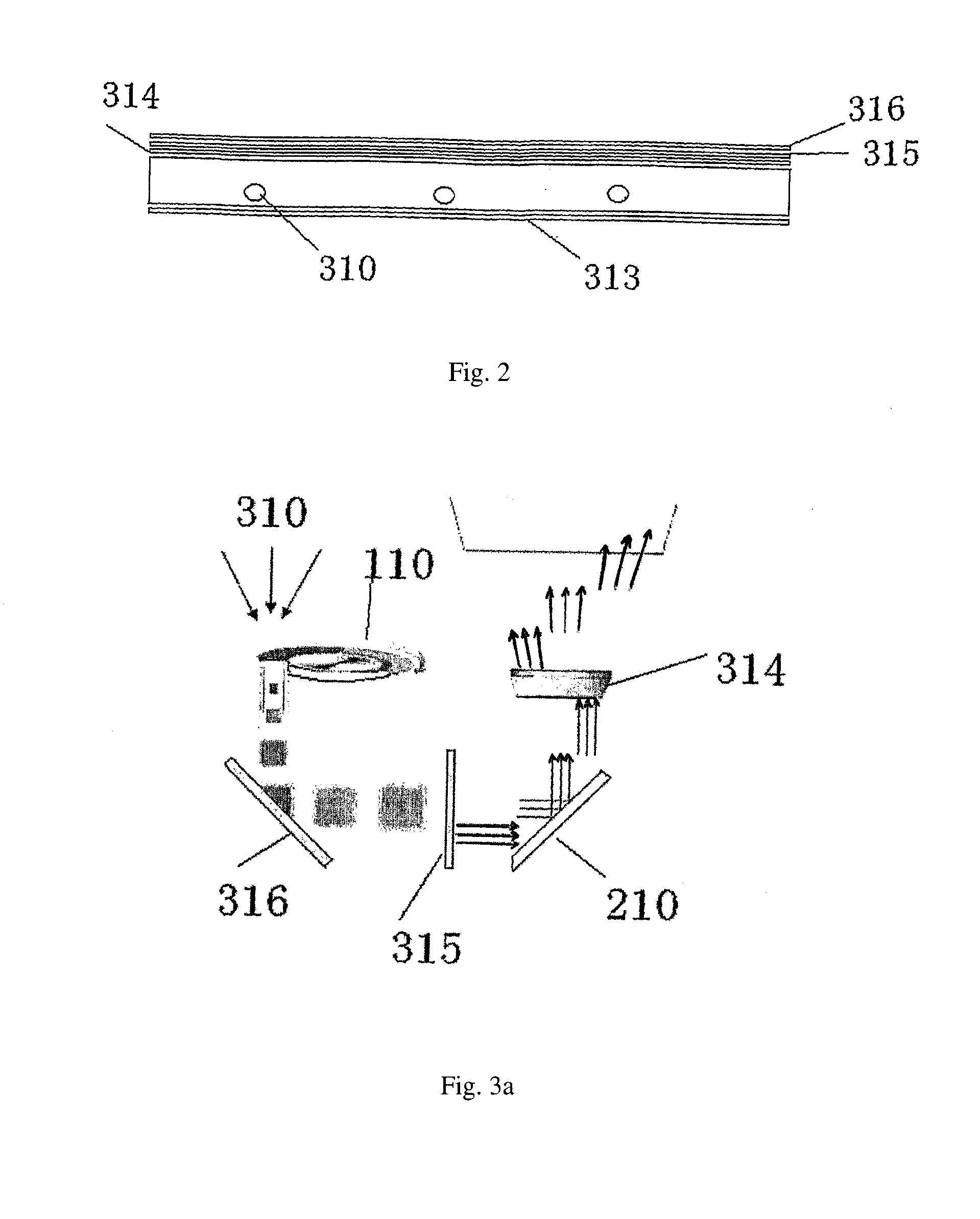
[0135]The operation is in that: the blue sub-pixels 110c′ of the photoluminescence film absorb the ultraviolet light and emit a blue light (400-500 nm), and the light emitted depends on the photoluminescence efficiency of the luminescent material; the green sub-pixels of the photoluminescence film absorb the ultraviolet light and emit a green light (500-570 nm), and the green light emitted depends on the photoluminescence efficiency of the luminescent material; the red sub-pixels of the...


PUM

PropertyMeasurementUnit
wavelengthaaaaaaaaaa
photoluminescence quantum efficiencyaaaaaaaaaa
distanceaaaaaaaaaa

Abstract

A display apparatus (100′) includes a substrate (115a) and a light switch (210). A light source (310′) is provided at the side of the substrate (115a) and emits light of which wavelength is in the range of ultraviolet or cyan. A polarizing sheet (116), as well as a photoluminescence film (110′), is provided in front of the light source (310′). Under the excitation of the light source (310′), the photoluminescence film (110′) can emit red light, green light, blue light and/or intermediate color light among red, green and blue.

Description

TECHNICAL FIELD[0001]The present invention relates to a display device and a cellular phone, a computer and a television including the same.BACKGROUND[0002]Liquid crystal displays (LCD) are used in a wide range from 1 inch scaled cellular phones to 40 inches scaled or larger television sets as well as in computers. A liquid crystal display comprises a liquid crystal cell, peripheral driving IC (Intergrated Circuit) and circuits, a light source and related mechanisms behind the liquid crystal cell. The initially used liquid crystal display was dominantly of passive driven TN (Twisted Nematic) and STN (Super Twisted Nematic) types, but the currently dominant type is a transmissive a-Si TFT (amorphous silicon thin-film transistor) active matrix (AM) driven LCD, i.e., a-Si TFT-AMLCD. Liquid crystal display monitors are generally used in a TN mode, whereas liquid crystal display television sets have a wide-angle mode such as IPS (In Plane Switching), MVA (Multi-domain Vertical Alignment)...

Claims


Application Information

Patent Timeline
Patent Type & Authority Applications(United States)
IPC IPC(8): G02F1/13357H04M1/00H04N9/30G09G5/00F21V7/04
CPCC09K11/7734C09K11/7738C09K11/7783H01L27/322G02F1/133553G02F1/133617G02F2202/38C09K11/7795H10K59/38
Inventor SUN, RUNWEN
Owner SUN RUNWEN
Why Eureka
Try Eureka