Radiation phase image radiographing apparatus

Inactive Publication Date: 2010-03-11
FUJIFILM CORP
View PDF4 Cites 45 Cited by
  • Summary
  • Abstract
  • Description
  • Claims
  • Application Information

AI Technical Summary

Benefits of technology

[0046]Further, if an arrangement area of the multiple radiation sources in an extending direction of a diffraction member of the diffraction grating is made smaller than an arrangement area of the radiation sources in a direction orthogonal to the extending direction, the size of the radiation emission unit may be reduced and the overall size of the apparatus may be reduced.
[0047]Still further, when all of the multiple radiation sources are disposed in a line in the direction orthogonal to the extending direction of the diffraction member of the diffraction grating, the size of the apparatus may further be reduced.
[0048]Further, among image signals detected by the radiation image detector, if only a

Problems solved by technology

Where parallel beam, such as synchrotron radiation is used, the planar shape described above does not pose any problems, but it gives rise to a problem in medical diagnostic applications and the like in which an X-ray source that radiates wide

Method used


Image

  • Radiation phase image radiographing apparatus
  • Radiation phase image radiographing apparatus
  • Radiation phase image radiographing apparatus

Examples


first embodiment

[0137]Next, a modification of the radiation phase image radiographing apparatus according to the present invention will be described.

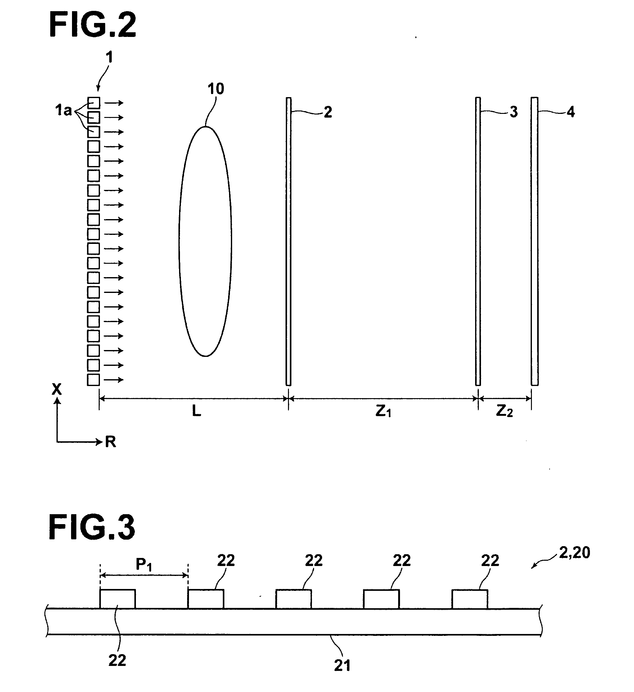
[0138]In the radiation phase image radiographing apparatus according to the first embodiment, radiation sources 1a are disposed along a planar surface, and first diffraction grating 2 and second diffraction grating 3 are formed along planar surfaces parallel to the planar surface on which multiple radiation sources 1a are disposed. But the structure is not limited to this, and an arrangement may be adopted in which radiation sources 1a are disposed along a cylindrical surface to form radiation emission unit 1, and first diffraction grating 2 and second diffraction grating 3 are formed along cylindrical surfaces concentric with the center O of the cylindrical surface on which multiple radiation sources 1a are disposed, as illustrated in FIG. 6. The arrangement of the radiation sources 1a along a cylindrical surface in the manner as described above may r...

second embodiment

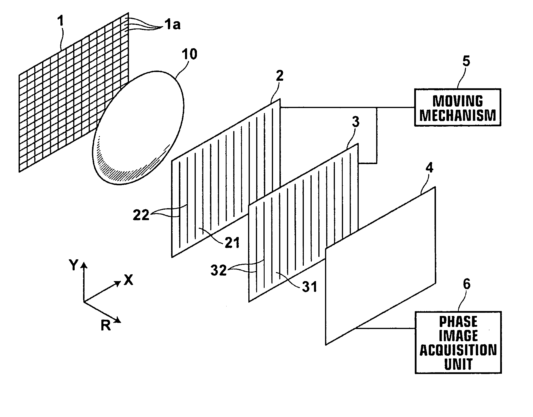
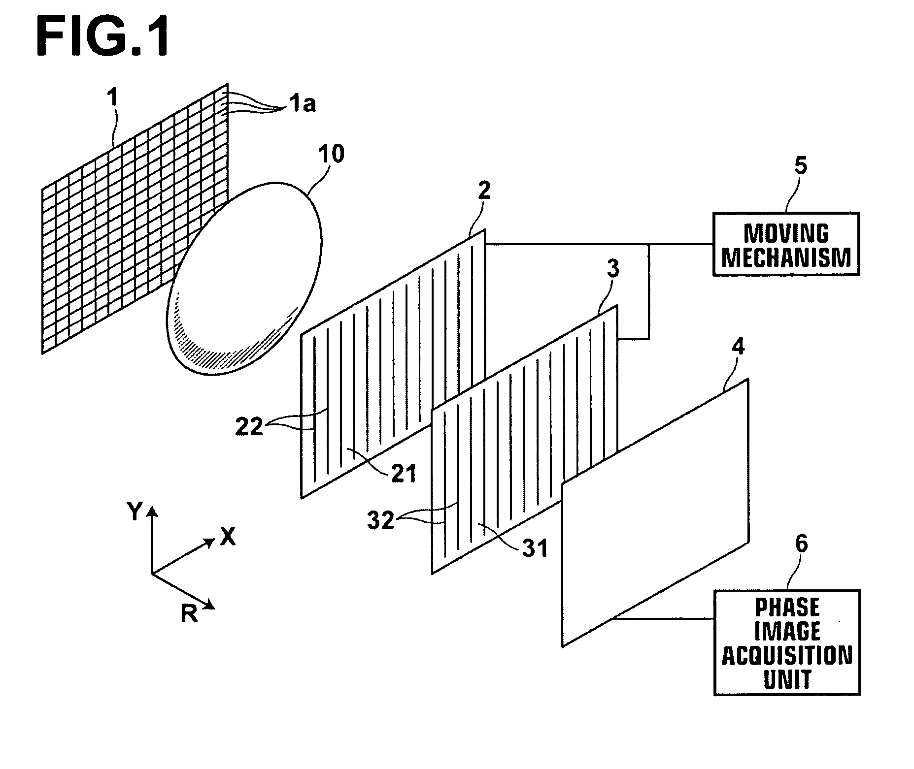
[0160]As illustrated in FIG. 13, the radiation phase image radiographing apparatus includes radiation emission unit 1 that emits radiation onto subject 10, diffraction grating 20 configured to be exposed to the radiation transmitted through subject 10 and to produce Talbot effect by the exposure, periodic information imaging radiation image detector 40 that detects periodic information of the radiation diffracted by diffraction grating 20, shifting mechanism 55 that shifts diffraction grating 20 and periodic information imaging radiation image detector 40 in a direction orthogonal to linear electrodes of detector 40 (X direction in FIG. 13) along respective planes, and phase image acquisition unit 6 that forms a phase image based on an image signal detected by periodic information imaging radiation image detector 40.

[0161]Radiation emission unit 1 has an identical structure to those of the first embodiment and the modifications thereof.

[0162]Diffraction grating 20 has an identical ...

third embodiment

[0243]As illustrated in FIGS. 30A to 30C, periodic information imaging radiation image detector 200 of the radiation phase image radiographing apparatus includes the following stacked in the order listed below: first electrode layer 201 that transmits radiation; recording photoconductive layer 202 that generates charges by receiving radiation transmitted through first electrode layer 201; charge transport layer 204 that acts as an insulator against charges of one polarity of those generated in recording photoconductive layer 202 and as a conductor for charges of the other polarity; readout photoconductive layer 205 that generates charges by receiving readout light; and second electrode layer 206. Storage section 203 for storing charges generated in recording photoconductive layer 202 is formed adjacent to the interface between recording photoconductive layer 202 and charge transport layer 204. Each of the layers described above is stacked on glass substrate 207 one after another fr...


PUM


Abstract

A radiation phase image radiographing apparatus, including a radiation emission unit having multiple radiation sources for emitting radiation onto a subject, the radiation sources being distributed such that radiation emitted from each of the radiation sources and transmitted through the subject forms a part of a projected image of the subject, a first diffraction grating configured to be exposed to the radiation emitted from the multiple radiation sources of the radiation emission unit and to produce a Talbot effect by the exposure, a second diffraction grating for diffracting the radiation diffracted by the first diffraction grating, and a radiation image detector for detecting the radiation diffracted by the second diffraction grating.

Description

BACKGROUND OF THE INVENTION[0001]1. Field of the Invention[0002]The present invention relates to a radiation phase image radiographing apparatus using a Talbot interferometer.[0003]2. Description of the Related Art[0004]The use of a Talbot interferometer, which produces Talbot effect by a diffraction grating and generates Moire fringes in combination with another diffraction grating, to X-ray applications has been studied as described, for example, in U.S. Pat. No. 5,812,629 (Patent Document 1) and U.S. Pat. No. 7,180,979 (Patent Document 2).[0005]For example, Patent Document 2 proposes an X-ray imaging apparatus using a Talbot interferometer that includes an X-ray source, two diffraction gratings, and an X-ray image detector.[0006]In the X-ray imaging apparatus described in Patent Document 2, both the two diffraction gratings and X-ray image detector are formed on a planar substrate. Where parallel beam, such as synchrotron radiation is used, the planar shape described above does n...

Claims


Application Information

Patent Timeline
IPC IPC(8): G01T1/36
CPCG21K2201/06G21K2201/064G21K2201/067G21K2207/005A61B6/00G21K1/06A61B6/4014A61B6/4233A61B6/466A61B6/484G03B42/026A61B6/032
Inventor TAKAHASHI, KENJI
Owner FUJIFILM CORP
Why Eureka
Try Eureka