
Electroactive biopolymer optical and electro-optical devices and method of manufacturing the same

a biopolymer and optical technology, applied in the direction of peptides, textiles and paper, conductive materials, etc., can solve the problems of non-biodegradable materials, long time in the environment, and increased environmental pollution, so as to reduce environmental pollution, improve environmental protection, and improve environmental protection

Active Publication Date: 2010-03-18
TRUSTEES OF TUFTS COLLEGE
View PDF54 Cites 93 Cited by
  • Summary
  • Abstract
  • Description
  • Claims
  • Application Information

AI Technical Summary

Benefits of technology

The present invention provides biopolymer optical devices and methods for manufacturing them that offer various functional features and are environmentally friendly. The invention also provides new methods for incorporating conducting polymers into biopolymers, which can be used for electronic properties and optical functions. The technical effects of the invention include providing innovative solutions for creating biopolymer optical devices with improved performance and functionality, as well as providing new options for forming conformal, light weight, functional protective coatings with enhanced electronic and optical functions for a variety of applications.

Problems solved by technology

However, these optical devices, and the fabrication methods employed in their manufacture, generally involve significant use of non-biodegradable materials.
Such materials are not biodegradable and remain in the environment for extended periods of time after the optical devices are removed from service and discarded.
However, recycling also requires expenditures of natural resources and adds to the environmental costs associated with such materials.
Therefore, there exists an unfulfilled need for optical devices that minimize the negative impact to the environment.
In addition, there exists an unfulfilled need for optical devices that provide additional functional features that are not provided by conventional optical devices.

Method used


Image

  • Electroactive biopolymer optical and electro-optical devices and method of manufacturing the same
  • Electroactive biopolymer optical and electro-optical devices and method of manufacturing the same
  • Electroactive biopolymer optical and electro-optical devices and method of manufacturing the same

Examples


Embodiment Construction

[0040]In view of the superior functional characteristics and processability noted above, the biopolymer optical devices in accordance with the present invention are described as being fabricated using a biopolymer such as silk. In this regard, the silk utilized was silkworm silk. However, there are many different silks, including spider silk, transgenic silks, and genetically engineered silks, variants and combinations thereof and others, that may alternatively be used to manufacture biopolymer optical devices in accordance with the present invention.

[0041]In addition, other biodegradable polymers may be used instead of silk. For example, other biopolymers, such as chitosan, exhibit desirable mechanical properties, can be processed in water, and form generally clear films for optical applications. Other biopolymers, such as collagen, cellulose, chitin, hyaluronic acid, amylose, and the like may alternatively be utilized in specific applications. Synthetic biodegradable polymers such...


PUM

PropertyMeasurementUnit
RMS surface roughnessaaaaaaaaaa
thicknessaaaaaaaaaa

Abstract

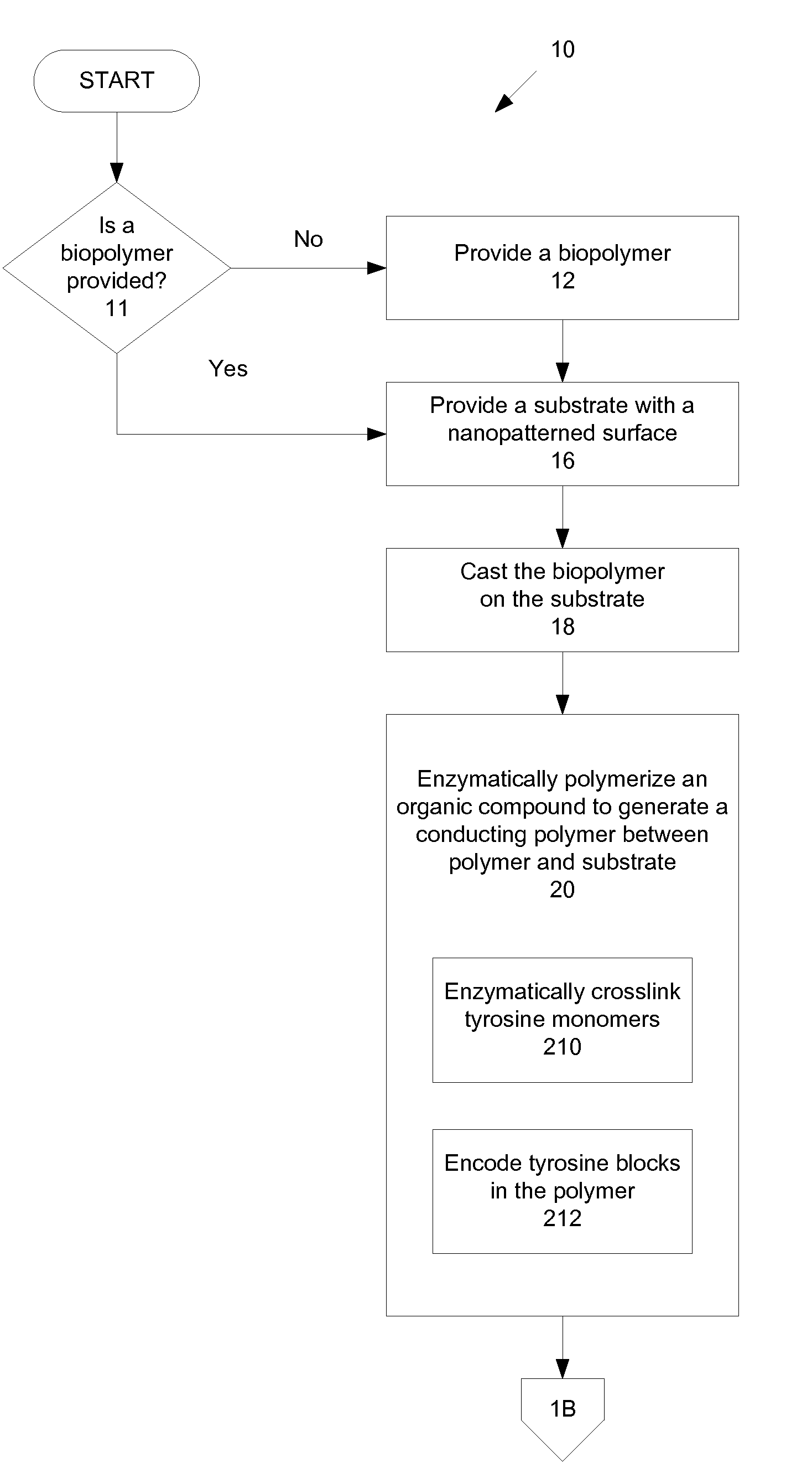
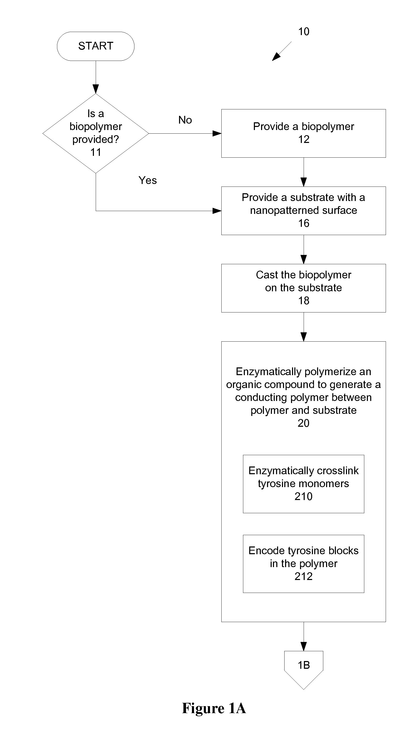
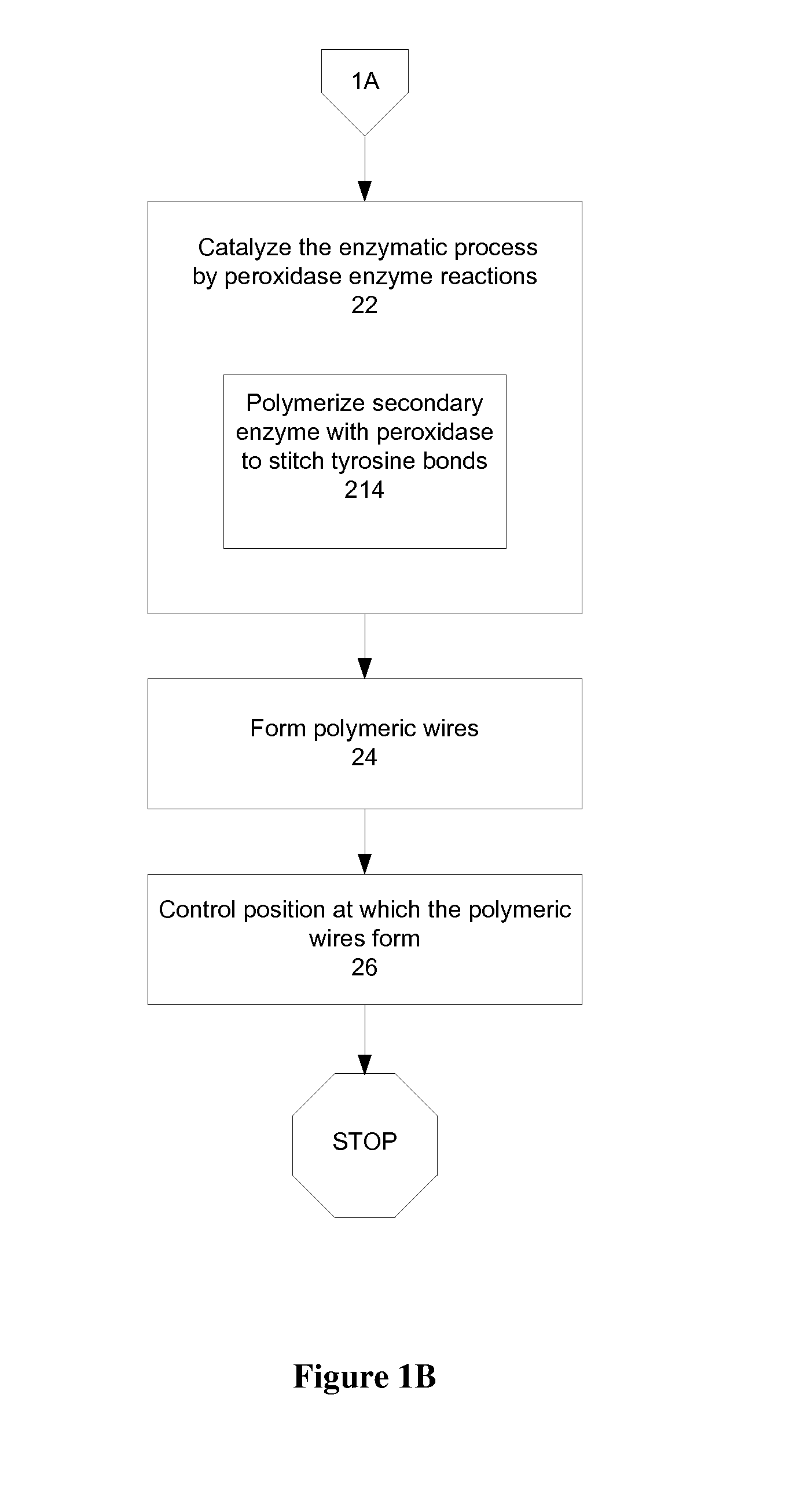
A method of manufacturing a biopolymer optical device includes providing a polymer, providing a substrate, casting the polymer on the substrate, and enzymatically polymerizing an organic compound to generate a conducting polymer between the provided polymer and the substrate. The polymer may be a biopolymer such as silk and may be modified using organic compounds such as tyrosines to provide a molecular-level interface between the provided bulk biopolymer of the biopolymer optical device and a substrate or other conducting layer via a tyrosine-enzyme polymerization. The enzymatically polymerizing may include catalyzing the organic compound with peroxidase enzyme reactions. The result is a carbon-carbon conjugated backbone that provides polymeric “wires” for use in polymer and biopolymer optical devices. An all organic biopolymer electroactive material is thereby provided that provides optical functions and features.

Description

CROSS-REFERENCE TO RELATED APPLICATIONS[0001]This application claims the benefit of priority of U.S. Provisional Application Ser. No. 60 / 856,297 filed on Nov. 3, 2006, entitled “Biopolymer Devices and Methods for Manufacturing the Same.”GOVERNMENT SUPPORT[0002]The invention was made with government support under grant number FA95500410363 awarded by the Air Force Office of Scientific Research. The government has certain rights in this invention.BACKGROUND OF THE INVENTION[0003]1. Field of the Invention[0004]The present invention is directed to electroactive biopolymer optical and electro-optical devices and methods for manufacturing such devices. The present invention is further directed to electronics and electrical integration to biopolymer optical and electro-optical devices.[0005]2. Description of Related Art[0006]The field of optics is well established. Some subfields of optics include diffractive optics, micro-optics, photonics and guided wave optics. Various optical devices h...

Claims


Application Information

Patent Timeline
Patent Type & Authority Applications(United States)
IPC IPC(8): H01B1/12G02B6/10
CPCB29C39/02B29D11/0074B82Y20/00G01N33/54386G02B1/046G02B6/138G02B2006/12102G02B2006/12104G02B2006/12107G02B2006/1213G02B2006/12171B29D11/00663G02B1/04G01N33/54373G02B1/06C07K14/43586D01F4/02D10B2211/04D10B2401/20G01N33/5436G01N33/544G01N2333/43578G02B1/005G02B1/041G02B1/045G02B5/18
Inventor KAPLAN, DAVID L.OMENETTO, FIORENZOLAWRENCE, BRIANCRONIN-GOLOMB, MARKGEORGAKOUDI, IRENE
Owner TRUSTEES OF TUFTS COLLEGE
Learn More