Vector controller for permanent-magnet synchronous electric motor

a synchronous electric motor and controller technology, applied in the direction of electric generator control, dynamo-electric converter control, dynamo-electric gear control, etc., can solve the problem of complex operation, excessive increase of magnetic field-direction current correcting value, etc., and achieve high speed range

Inactive Publication Date: 2010-03-18
MITSUBISHI ELECTRIC CORP
View PDF9 Cites 97 Cited by
  • Summary
  • Abstract
  • Description
  • Claims
  • Application Information

AI Technical Summary

Benefits of technology

[0010]A vector controller for a permanent-magnet synchronous electric motor, according to the invention, controls an alternating current from an inverter that drives the permanent-magnet synchronous electric motor so as to come into coincidence with a current command, and provided with a reference phase-angle calculation unit for generating a reference phase angle of the permanent-magnet synchronous electric motor; a current command generation unit for generating the current command using a given torque command; a current control unit for making a control calculation of a current error between the current command and a current through the permanent-magnet synchronous electric motor, to output the calculated current error; a decoupling voltage calculation unit for calculating a feed-forward voltage using motor parameters of the permanent-magnet synchronous electric motor and the current command; a modulation index calculation unit for outputting a modulation index for the inverter by receiving a direct-...

Problems solved by technology

For that reason, when the voltage command theoretically calculated based on the current command cannot be set to a value smaller than the voltage command set anew—for example, when a torque command is excessively large for rotation speed of the electric motor—even though a magnetic-field-direction current is corrected using the magnetic-field-direction current correcting value, the difference between the voltage command and the voltage command set anew cannot be set to zero and the integration va...

Method used


Image

  • Vector controller for permanent-magnet synchronous electric motor
  • Vector controller for permanent-magnet synchronous electric motor
  • Vector controller for permanent-magnet synchronous electric motor

Examples


embodiment 1

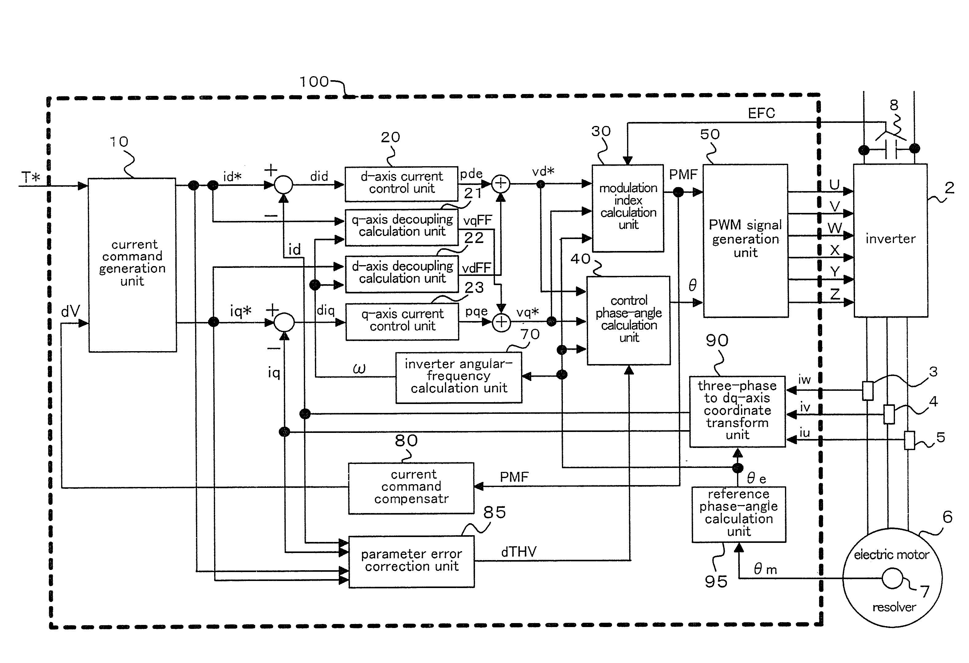
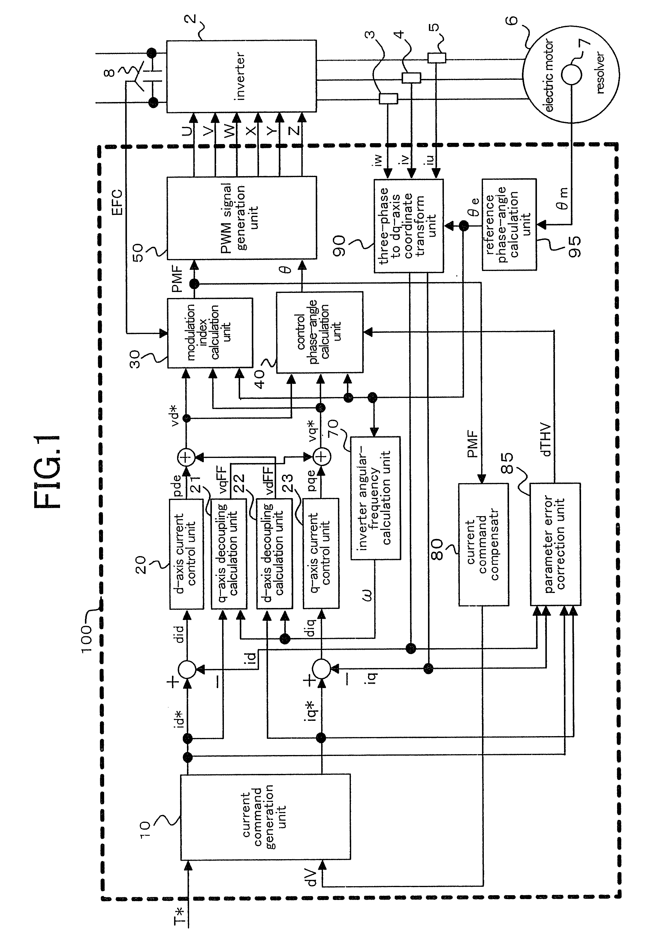
[0057]FIG. 1 is a block diagram illustrating an example of a configuration of a vector controller for a permanent-magnet synchronous motor, according to Embodiment 1 of the present invention. As shown in FIG. 1, a main circuit is configured with a capacitor 1 that is a direct-current power source, an inverter 2 that converts direct-current voltage of the capacitor 1 into an alternating-current voltage of any given frequency, and a permanent-magnet synchronous electric motor 6 (hereinafter, simply referred to as “electric motor”).

[0058]The main circuit is also provided with a voltage sensor 8 that senses voltage of the capacitor 1, current sensors 3, 4, and 5 that sense currents iu, iv, and iw through the output lines of the inverter 2. The electric motor 6 is provided with a resolver 7 that senses a rotor mechanical angle θm. Each of these sensing signals is input into a vector controller 100.

[0059]The resolver 7 may be substituted with an encoder, or a position sensorless method ma...


PUM


Abstract

A method of controlling a current command by comparing voltage with a set value needs to vary the set value depending on voltage fluctuation, which involves taking a complicated control. A vector controller for a permanent-magnet synchronous electric motor, according to the present invention, can realize with a simplified configuration a field-weakening operation in a one-pulse mode in a high speed range by providing a current command compensator that corrects a current command by a corrected current command calculated based on a modulation index.

Description

TECHNICAL FIELD[0001]The present invention relates to vector controllers for permanent-magnet synchronous electric motors.BACKGROUND ART[0002]Vector control technologies for permanent-magnet synchronous electric motors (hereinafter abbreviated as “electric motor”) using an inverter are widely employed in industry. By separately controlling the magnitude and the phase of inverter output voltage, a current vector in an electric motor is optimally controlled, so that torque of the electric motor is fast and instantaneously controlled. Permanent-magnet synchronous electric motors are known as high-efficiency electric motors in comparison with induction motors because no energizing current is needed due to establishment of magnetic field by the permanent magnet and no secondary copper loss is generated due to no rotor current. For that reason, application of permanent-magnet synchronous electric motors to electric railcars has been investigated in recent years.[0003]Subjects with control...

Claims


Application Information

Patent Timeline
IPC IPC(8): H02P21/06H02P27/04H02P21/00H02P21/13H02P21/22H02P27/08
CPCB60L11/1803B60L15/025B60L2220/14H02P4/00H02P21/0085B60L2200/26H02P21/06H02P27/04Y02T10/643Y02T10/7005Y02T10/7258H02P21/0089B60L50/51Y02T10/64Y02T10/70Y02T10/72B60L15/20H02P21/00
Inventor KITANAKA, HIDETOSHI
Owner MITSUBISHI ELECTRIC CORP
Why Eureka
Try Eureka