
System and process for producing high-pressure hydrogen

a hydrogen production system and high-pressure technology, applied in the field of high-pressure hydrogen production, can solve the problems of inability to supply fuel cell-quality hydrogen economically viable, difficulty in hydrogen production and cost, and inability to meet the needs of hydrogen storage and transportation,

Active Publication Date: 2010-03-18
ENERGY & ENVIRONMENTAL RES CENT FOUNDATIO
View PDF2 Cites 8 Cited by
  • Summary
  • Abstract
  • Description
  • Claims
  • Application Information

AI Technical Summary

Benefits of technology

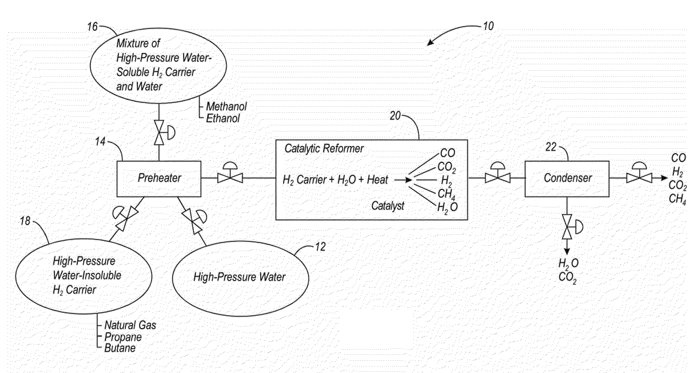
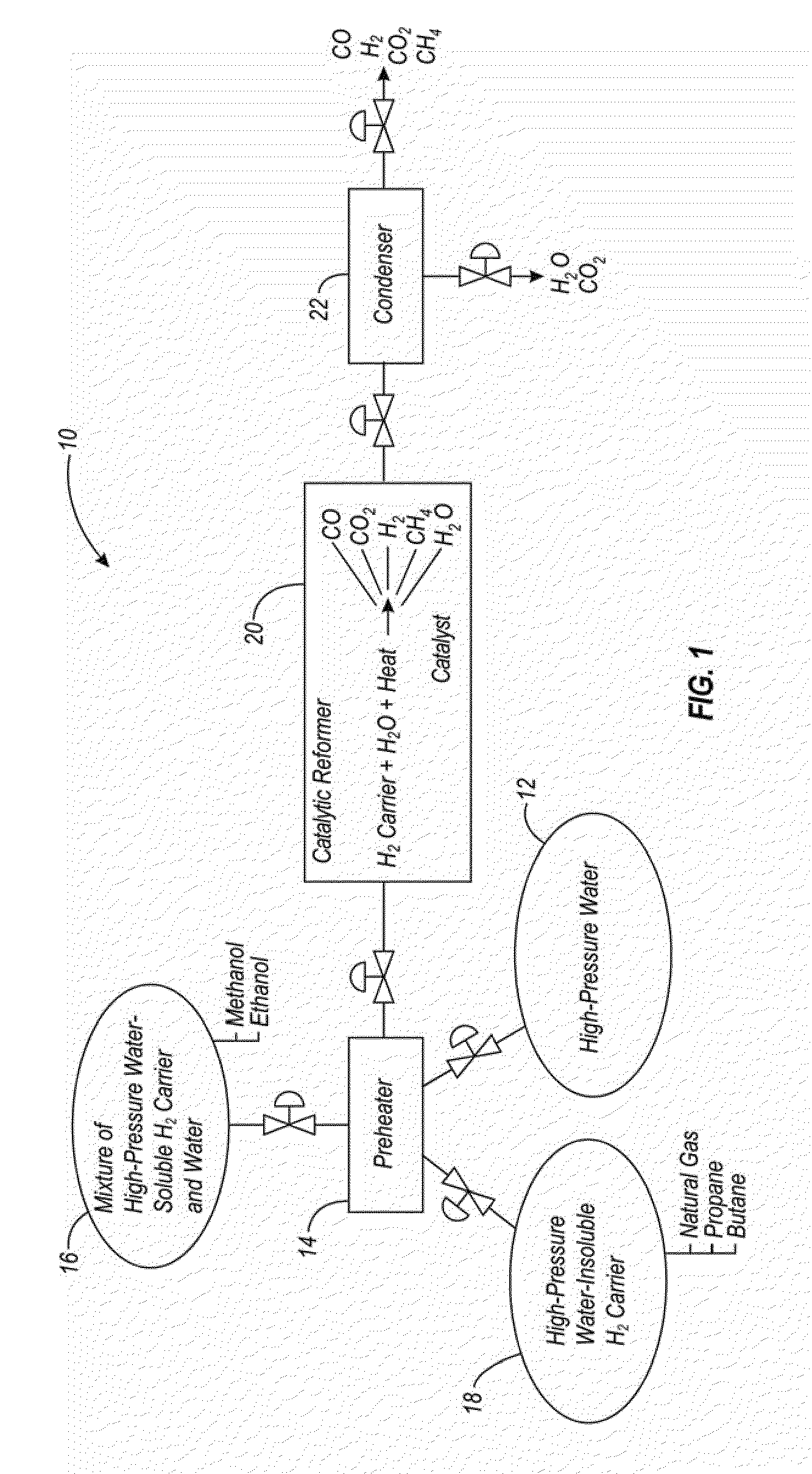
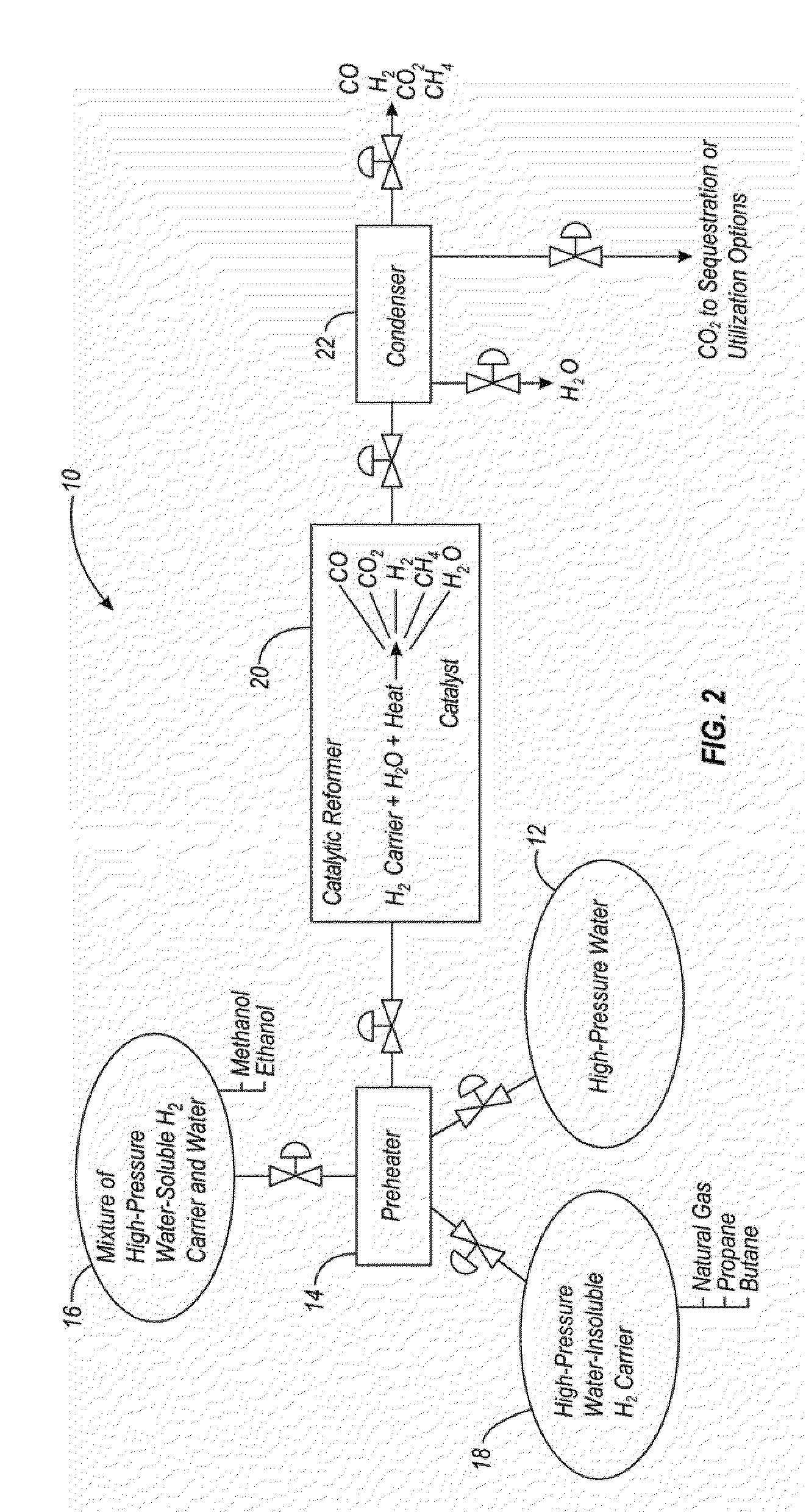
[0009]An apparatus and method are provided for producing high-pressure hydrogen on-demand. The invention uses a mixture of hydrocarbon carrier with or without high-pressure water exposed to a catalyst under high-pressure conditions to produce high-pressure hydrogen. In one embodiment, carbon dioxide that is produced can be separated and recovered for sequestration or other utilization options. In another example, the apparatus can be integrated with a fuel cell to provide hydrogen to the fuel cell, while the fuel cell provides heat to help maintain desired conditions in the hydrogen production reactor.

Problems solved by technology

One problem is a lack of an economically viable means of supplying fuel cell-quality hydrogen.
Typical fuel cells require a relatively pure form of hydrogen, which makes the hydrogen production more difficult and costly.
Another problem relates to hydrogen storage and transportation.
Because of its small molecular size, hydrogen is much more difficult and expensive to compress than natural gas, for example.
Typical prior art hydrogen production techniques require the costly step of pressurizing the hydrogen after it is produced.
Challenges associated with on-site hydrogen generation derive from the unpredictable demands of vehicle fueling.
Because SMR works best at a steady-state, 24-hours-a-day, full-capacity operation, integration with a hydrogen fuel station will require costly on-site hydrogen compression and storage (as a gas, a liquid, or in a chemical compound) to compensate for fluctuating hydrogen demand.
None of the hydrogen storage technologies available today represents an ideal combination of economy, performance, durability, and safety.
Processes that require a high temperature are less desirable since more energy is expended during the process.
Similarly, typical prior art processes that produce hydrogen have the disadvantage of requiring pressurization after the hydrogen is produced, since vehicle-fuel hydrogen must be compressed to enable sufficient fuel for a desirable range (e.g., 300 miles).

Method used


Image

  • System and process for producing high-pressure hydrogen
  • System and process for producing high-pressure hydrogen
  • System and process for producing high-pressure hydrogen

Examples


Embodiment Construction

[0020]Generally, the present invention offers an apparatus and method of economically producing high-pressure hydrogen, thereby eliminating the need for expensive hydrogen compression. In addition, the present invention can be used for on-demand production of high-pressure hydrogen, which results in greatly diminished hydrogen storage volume requirements compared to other systems, such as SMR and other demand-unresponsive processes. The present invention can produce high-pressure hydrogen from natural gas, methanol, ethanol, and other fossil fuel-derived and renewable hydrocarbon resources, including oxygen- and nitrogen-containing hydrocarbons. The process can produce hydrogen at pressures ranging from 2000 to 12,000 pounds per square inch (psi) using a hydrogen carrier, with or without water, and a catalyst under high-pressure, moderate-temperature reaction conditions. Note that this pressure range is only one example and that higher pressures could also be used. In one example, w...


PUM


Abstract

A method and apparatus are provided for use in producing high-pressure hydrogen from natural gas, methanol, ethanol, or other fossil fuel-derived and renewable hydrocarbon resources. The process can produce hydrogen at pressures ranging from 2000 to 12,000 pounds per square inch (psi) using a hydrogen carrier, with or without high-pressure water, and an appropriate catalyst. The catalyst reacts with the hydrogen carrier and, optionally, high-pressure water, in a catalytic reformer (20) maintained under desired temperature and pressure conditions.

Description

CROSS REFERENCE TO RELATED APPLICATIONS[0001]This application is a CIP of co-pending commonly owned U.S. patent application Ser. No. 10 / 553,531, attorney docket number EER.P0017, filed on Oct. 14, 2005, entitled “SYSTEM AND PROCESS FOR PRODUCING HIGH-PRESSURE HYDROGEN,” (pending) which is incorporated by reference herein.[0002]“This invention was made with U.S. Government support under Cooperative Agreement No. W9132T-08-2-0014 awarded by the U.S. Army Construction Engineering Research Laboratory. The Government has certain rights in this invention.”FIELD OF THE INVENTION[0003]This invention relates to the field of hydrogen production. In particular, this invention is drawn to a system and method of producing high-pressure hydrogen on-demand, using a catalytic reformer under high-pressure conditions.BACKGROUND OF THE INVENTION[0004]There are numerous proposals to transition from the current fossil fuel-based transportation systems to what is known as the “hydrogen economy.” A hydrog...

Claims


Application Information

Patent Timeline
IPC IPC(8): C01B3/26C01B3/04C01B31/20C01B31/18H01M8/06C01B32/40C01B32/50
CPCC01B3/323C01B2203/86C01B2203/0233C01B2203/0415C01B2203/042C01B2203/0475C01B2203/0495C01B2203/066C01B2203/1217C01B2203/1223C01B2203/1229C01B2203/1235C01B2203/1247C01B2203/148C01B3/38Y02P30/00
Inventor COLLINGS, MICHAELAULICH, TED R.TIMPE, RONALD C.HOLMES, MICHAEL J.
Owner ENERGY & ENVIRONMENTAL RES CENT FOUNDATIO
Learn More