
Unidirectionally-solidification process and castings formed thereby

a technology of unidirectional solidification and castings, which is applied in the direction of crystal growth process, machine/engine, mechanical equipment, etc., can solve the problems of inability to produce stage buckets and other castings with lengths exceeding one hundred centimeters (and correspondingly large cross-sections and weights) previously, and achieve the effect of fr

Inactive Publication Date: 2010-03-25
GENERAL ELECTRIC CO
View PDF5 Cites 8 Cited by
  • Summary
  • Abstract
  • Description
  • Claims
  • Application Information

AI Technical Summary

Benefits of technology

"The present invention provides a process for producing metallic castings with unidirectional crystal structures that are long (up to one hundred centimeters or more) and substantially free of freckle defects. The process involves directionally solidifying a molten metal alloy in a preheated mold and then cooling it to produce the casting. The unidirectional crystal structure formed by this process has a columnar single crystal microstructure or columnar polycrystalline microstructure, and it is well-suited for components of gas turbines, such as buckets and nozzles. The process allows for the production of castings that are longer, have larger cross-sections, and have greater weights than previous techniques. The absence of freckling in the castings is also a significant advantage."

Problems solved by technology

In particular, heat-treatable, freckle-free last stage buckets of land-based gas turbines can be produced to have single-crystal and directionally-solidified microstructures by this process, whereas last-stage buckets and other castings with lengths exceeding one hundred centimeters (and correspondingly large cross-sections and weights) were previously not possible.

Method used


Image

  • Unidirectionally-solidification process and castings formed thereby
  • Unidirectionally-solidification process and castings formed thereby
  • Unidirectionally-solidification process and castings formed thereby

Examples


Embodiment Construction

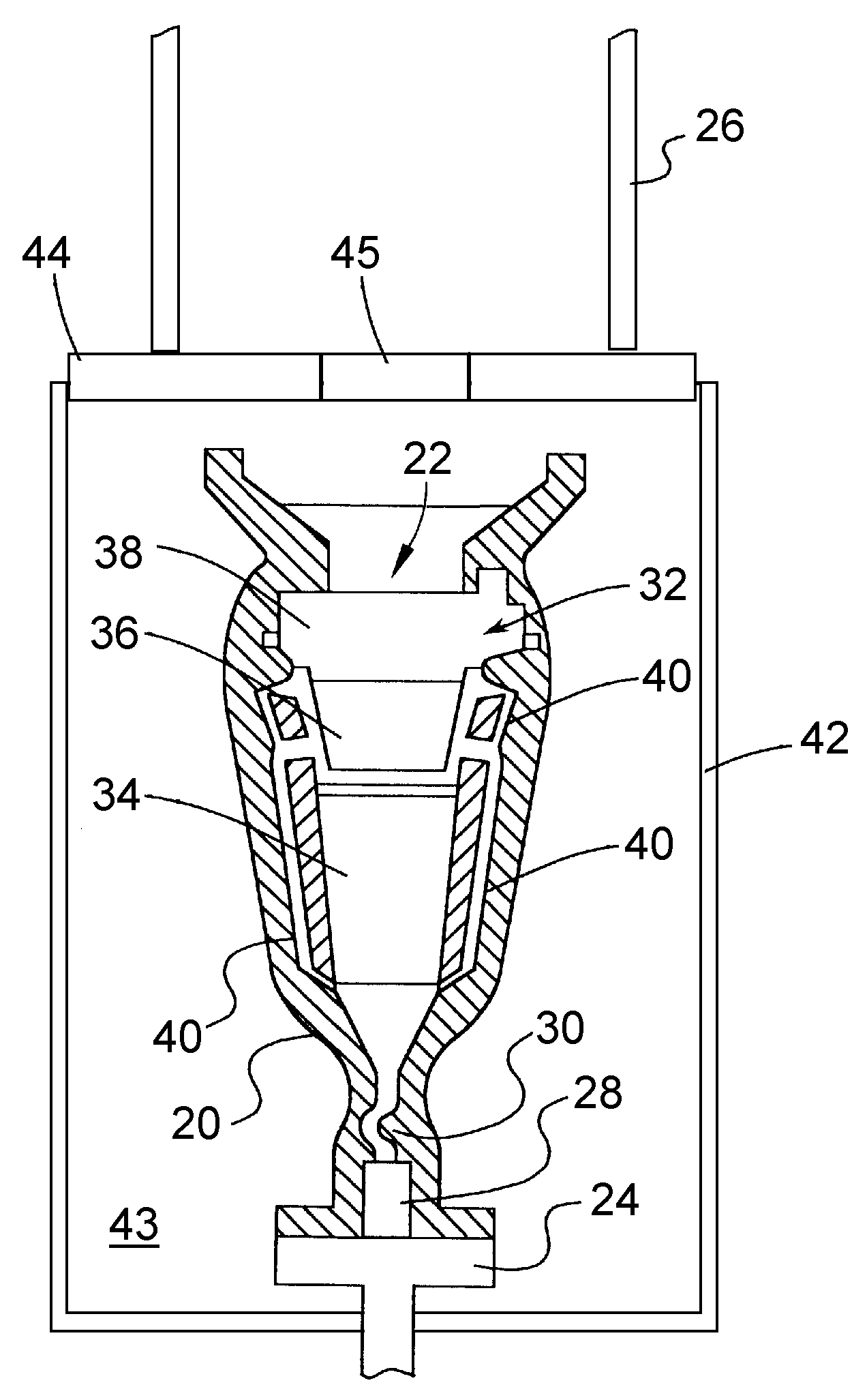
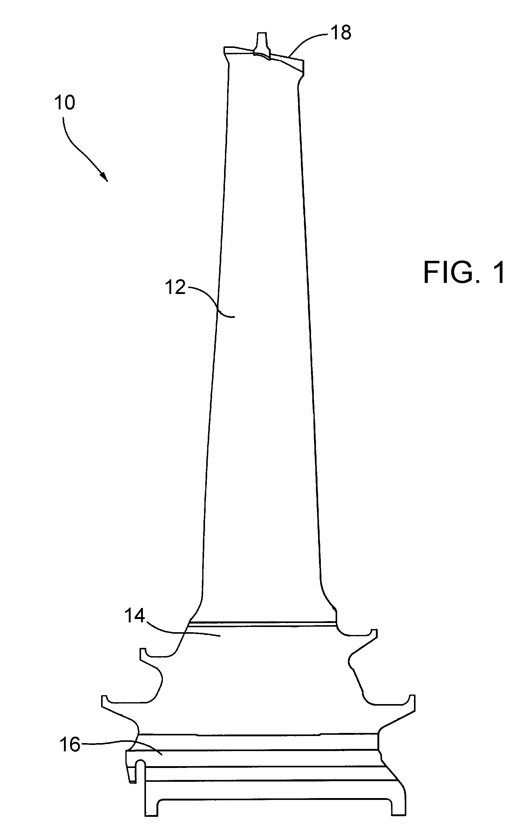
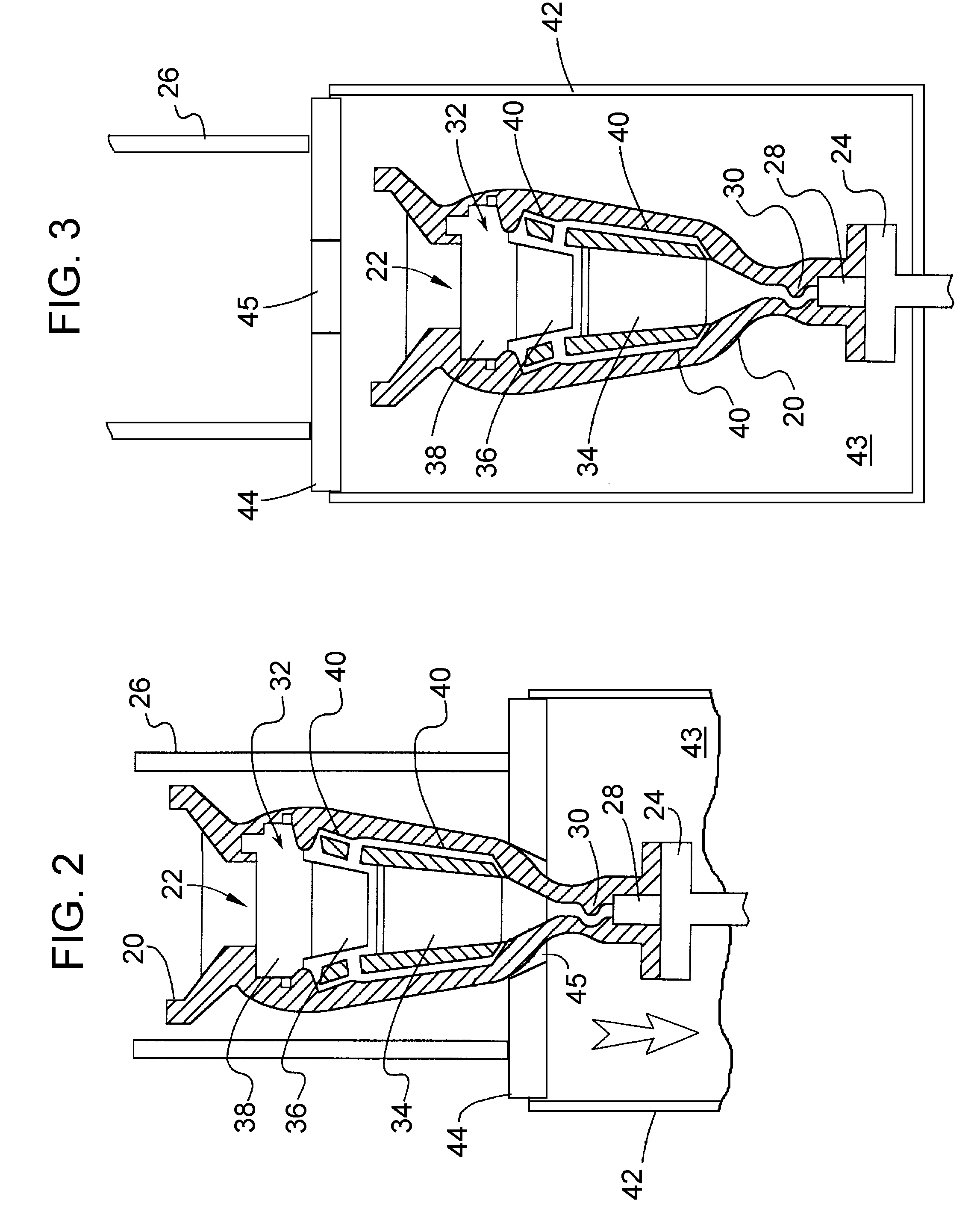
[0017]The present invention provides for the capability of producing unidirectionally-solidified castings beyond the capabilities and expectations of prior directional casting technologies. The invention builds upon a discovery disclosed in commonly-assigned U.S. Pat. No. 6,217,286 that certain solidification process conditions, as evidenced by dendrite arm spacing, are capable of preventing freckles in castings of up to forty inches (about one hundred centimeters) in length. The capability provided by the present invention was unexpected from U.S. Pat. No. 6,217,286, as evident from the teachings of this patent. Particularly unexpected was the ability to achieve and maintain a sufficient thermal gradient capable of forming primary dendrite arms with an acceptable arm spacing that would result in the prevention of freckling. Because the thermal gradient is dependent on the cooling rate and solidification rate (approximately equal to the withdrawal rate) of the casting process (a sim...


PUM

PropertyMeasurementUnit
lengthaaaaaaaaaa
sizeaaaaaaaaaa
massaaaaaaaaaa

Abstract

A process capable of producing large metallic castings having lengths of one hundred centimeters or more and a unidirectional crystal structure substantially free of freckle defects. The process includes pouring a molten metal alloy into a preheated mold within a heating zone, withdrawing the mold from the heating zone, through a heat shield, and into a cooling zone to directionally solidify the molten metal alloy, and then cooling the mold to produce the casting and the unidirectional crystal structure thereof. The heat shield operates as a barrier to thermal radiation between the heating zone and the cooling zone, and the mold is withdrawn at a rate that, in combination with the heat shield, maintains a thermal gradient to solidify the molten metal alloy and form primary dendrite arms having an average spacing therebetween of about 150 to about 500 micrometers.

Description

BACKGROUND OF THE INVENTION[0001]The present invention generally relates to materials and processes for producing directionally-solidified castings, and particularly to reducing defects in alloys cast as single-crystal (SX) and directionally-solidified (DS) articles suitable for use as components of gas turbines and other high temperature applications.[0002]Components of gas turbines, such as blades (buckets), vanes (nozzles) and combustor components, are typically formed of nickel, cobalt or iron-base superalloys characterized by desirable mechanical properties at turbine operating temperatures. Because the efficiency of a gas turbine is dependent on its operating temperatures, there is a demand for components, and particularly turbine buckets, nozzles, combustor components, and other hot gas path components, that are capable of withstanding higher temperatures. As the material requirements for gas turbine components have increased, various processing methods and alloying constitue...

Claims


Application Information

Patent Timeline
Patent Type & Authority Applications(United States)
IPC IPC(8): C22C19/03B22D27/04
CPCB22D27/045C30B11/003F05C2253/083F05B2230/21C30B29/52
Inventor SCHAEFFER, JON CONRADBALSONE, STEPHEN JOSEPHELLIOTT, ANDREW J.
Owner GENERAL ELECTRIC CO
Learn More