Intake air heating system of combined cycle plant

a combined cycle and heating system technology, applied in the direction of machines/engines, mechanical equipment, combustion air/fuel air treatment, etc., can solve the problems of difficult ignition of gas turbines, low combustion efficiency, and low combustion efficiency of gas turbines, so as to improve the ignition performance of gas turbines, prevent icing and surging, and prevent combustion vibration

Active Publication Date: 2010-04-15
MITSUBISHI POWER LTD
View PDF9 Cites 23 Cited by
  • Summary
  • Abstract
  • Description
  • Claims
  • Application Information

AI Technical Summary

Benefits of technology

[0070]According to the present invention, the heat exchanger is disposed in the air intake duct, and part of steam generated by the waste heat boiler is flowed through the heat exchanger, whereby intake air is heated. Thus, even extremely low temperature intake air can be effectively heated.
[0071]Since the effective heating of intake air can be achieved as described above, an improvement in the ignition performance of the gas turbine (ease of ignition), the prevention of combustion vibrations, and the prevention of icing and surging can be realized.
[0072]Hence, it becomes possible to operate the combined cycle plant, which utilizes a fuel gas of low calorific value, such as BFG, even in an extremely cold district.
[0073]Furthermore, only part of steam from the waste heat boiler is utilized for the heating of intake air. Thus, the system of the present invention does not adversely affect the combustion performance of the gas turbine, in comparison with an anti-icing system using gas turbine casing air.

Problems solved by technology

In installing the BFG-fired combined cycle plant in the extremely cold district, the following problems occur, because the calorific value of BFG is low and the air temperature of the atmosphere taken in is very low (e.g., −30° C.)
That is, under extremely low atmospheric temperature (e.g., −30° C.) conditions, it becomes difficult to ignite the gas turbine.
If the temperature of the air taken in is low, moisture in the low temperature air has a possibility to freeze or ice at the inlet of the compressor.
With this technology, however, air within the casing of the compressor is bled.
Thus, combustibility is adversely affected, and a large amount of air cannot be bled, so that the range of a rise in the intake air temperature has been restricted.
Even if such a technology is applied to the BFG-fired combined cycle plant installed in the extremely cold district, it is impossible to ensure the amount of heating bleed air required for heating air at an extremely low temperature (e.g., −30° C.
), because of limitations on the amount of bleed air.
This requires limitations on load, thereby ma king operation under heavy load difficult.

Method used


Image

  • Intake air heating system of combined cycle plant
  • Intake air heating system of combined cycle plant

Examples


Embodiment Construction

[0075]The best mode for carrying out the present invention will be described in detail based on its embodiment.

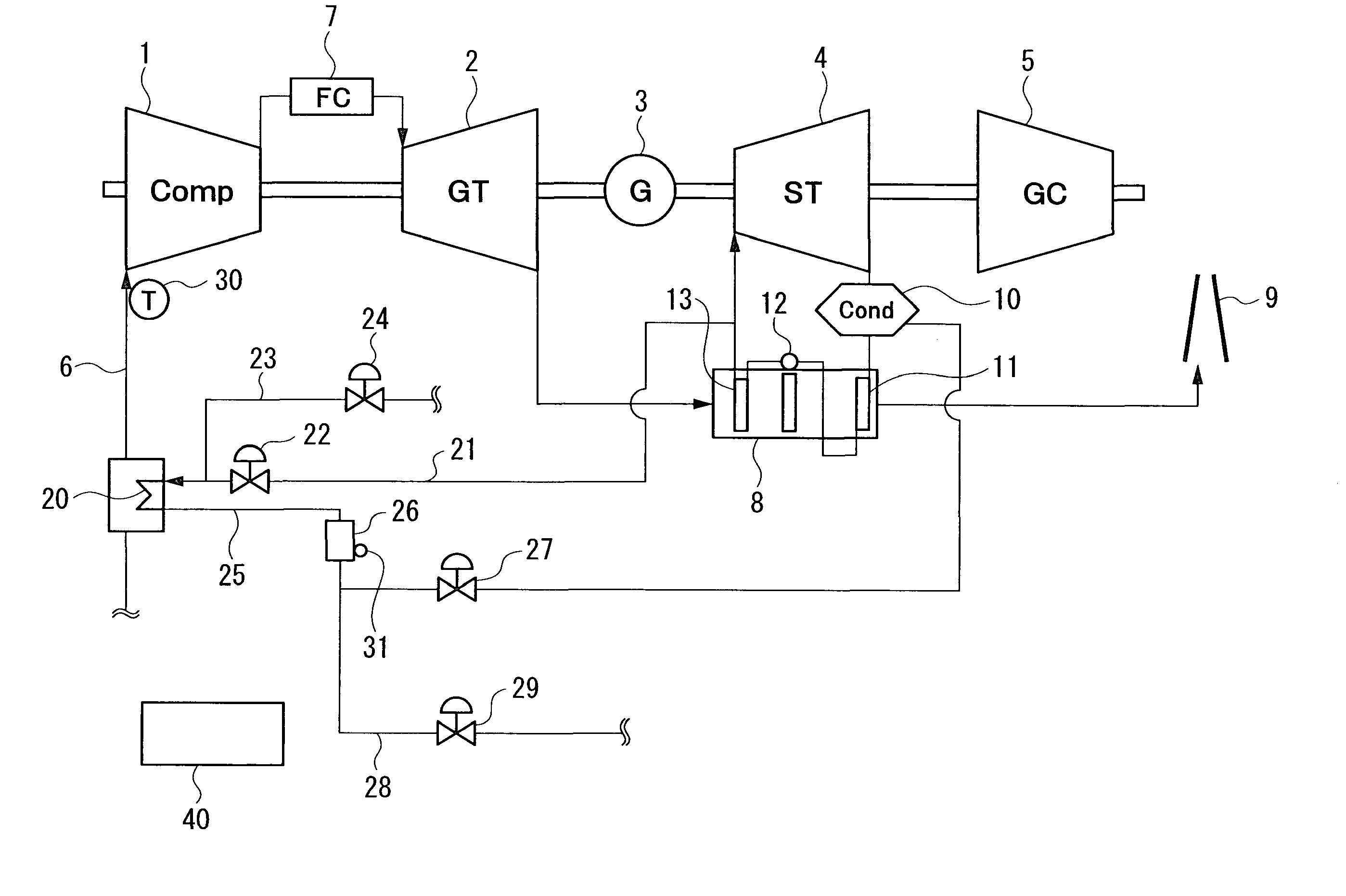
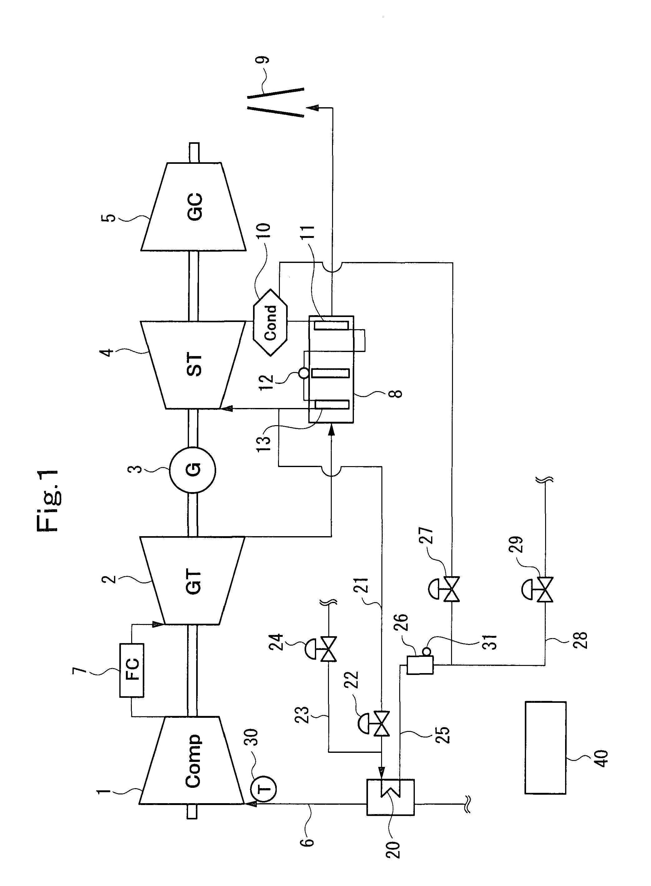
[0076]FIG. 1 is a system diagram showing a BFG-fired combined cycle according to an embodiment of the present invention.

[0077]In the present embodiment, a compressor 1, a gas turbine 2, an electric generator 3, a steam turbine 4, and a gas compressor 5 are provided on the same rotating shaft.

[0078]Compressed air, obtained when intake air taken in via an air intake duct 6 is compressed by the compressor 1, and BFG compressed by the gas compressor 5 are burned in a combustor 7. The gas turbine 2 is driven by a combustion gas formed by this combustion. An exhaust gas discharged from the gas turbine 2 has its heat recovered by a waste heat boiler 8, and steam is generated in the waste heat boiler 8. The exhaust gas having the heat recovered by the waste heat boiler 8 is discharged from a smokestack 9.

[0079]Steam generated by the waste heat boiler 8 is sent to the steam turbine ...


PUM


Abstract

A gas turbine 2 is driven by a combustion gas produced when BFG compressed by a gas compressor 5 and air compressed by a compressor 1 are burned in a combustor 7. Steam is generated from a waste heat boiler 8 by utilization of heat of an exhaust gas from the gas turbine 2, and a steam turbine 4 is driven by this steam. An electric generator 3 generates electricity upon driving of the turbines 2 and 4. A condensing heat exchanger 20 is disposed in an air intake duct 6, and part of steam from the waste heat boiler 8 is flowed through the heat exchanger 20 to heat intake air. The amount of steam flowed through the heat exchanger 20 is adjusted by the adjustment of the degree of opening of a steam control valve 22 by a control device 40. By so doing, the ignition performance of the gas turbine in a BFG-fired gas turbine combined cycle plant is enhanced even in an extremely cold district.

Description

BACKGROUND OF THE INVENTION[0001]1. Field of the Invention[0002]This invention relates to an intake air heating system of a combined cycle plant, which is designed, particularly, to be operable even in an extremely cold district.[0003]2. Description of the Related Art[0004]In an iron making process, a large amount of BFG (blast furnace gas) is formed in a blast furnace. In recent years, a BFG-fired combined cycle plant, which uses this BFG as a fuel for a gas turbine, has attracted attention from the viewpoints of environmental protection and effective utilization of energy.[0005]BFG is in a special fuel state such that it has a lower calorific value and contains larger amounts of impurities in the fuel, than a natural gas which is usually used as a gas turbine fuel.[0006]In the BFG-fired combined cycle plant, therefore, BFG is used as a fuel, with various ideas including, for example, the idea that BFG is compressed in a gas compressor directly connected to a gas turbine shaft, and...

Claims


Application Information

Patent Timeline
Patent Type & Authority Applications(United States)
IPC IPC(8): F02C7/04F02C6/18F01K23/10
CPCF01K23/10F01K23/101F02C3/22F02C6/18Y02E50/11F02C7/08F05D2220/75Y02E20/16F02C7/047Y02E50/10
Inventor HARADA, SHOICHI
Owner MITSUBISHI POWER LTD
Why Eureka
Try Eureka