
Motor Upgrade Kit For A Mechanical Press

a technology of mechanical presses and motors, which is applied in the direction of domestic applications, other domestic articles, hollow objects, etc., can solve the problems of long cycle time, low production rate, and complete operation at low speed, and achieve the limitation of kinetic energy of such a wheel, and reduce the kinetic energy of the wheel

Active Publication Date: 2010-04-15
ABB (SCHWEIZ) AG
View PDF14 Cites 12 Cited by
  • Summary
  • Abstract
  • Description
  • Claims
  • Application Information

AI Technical Summary

Benefits of technology

[0015]can be installed on an existing press in a very short time, on site
[0020]The Press Motor Upgrade Kit is a standalone unit which is mounted on the press in one part. It consists of a base plate, or base structure, which holds together the other parts of the kit, principally a motor and an associated transmission (eg gears). This structure or baseplate is fixed to the top or other structural part of the press crown, with sufficient mounting accuracy and rigidity. On the baseplate or structure is mounted the (servo) motor or motors. Through a coupling this motor is connected to gear wheels of the mechanical press, which gears will typically reduce the speed of the motor to a lower speed of an existing gear in the press crown. This connection will then allow the upgrade motor to move the press gears at variable speed, both in positive and negative direction and up to a higher speed (eg. 50% higher) when not stamping than the maximum stamping speed the mechanical press drive was originally designed for. Another advantage is the increased flexibility of production cycle made possible. For example, the hybrid servo technology described here allows pressing at lower speed while maintaining cycle time, or alternatively pressing at an identical speed but with shorter cycle time, or a mix of these two.
[0023]Thus, in its most typical form the Press Upgrade Kit will preferably be designed to interact with an intermediate gear of the existing mechanical press, since this gear is almost always closest to the top of the press crown (in a some cases it may even extend to above the top of the crown structure). It may seem a disadvantage that such an intermediate gear rotates at a lower speed than the main shaft, since a higher gear ratio is thus required in the transmission to a high-speed motor. However, to bridge the distance between the top of the intermediate gear wheel and the mounting point of a first gear wheel belonging to the kit, typically a relatively large-diameter gear wheel is needed. To limit the kinetic energy associated with such a wheel, it is advantageous that it turns at as low speed as possible. Thus, for a kit to add as little inertia to the press as possible, interfacing with an intermediate gear is in most cases preferable to interfacing with a main-shaft pinion.
[0025]The invention may be applied extensively, because adding a servo motor to an existing design is an option which can be applied to existing presses. Since presses typically have a life time of more than 30 years, this is a very important advantage. Many manufacturers and suppliers seek to upgrade or refurbish their existing press lines rather than investing in completely new lines.

Problems solved by technology

Thus, if pressing has to be done at a low speed (for quality or other technical reasons), the complete operation will occur at low speed.
This results in a long cycle time, and therefore, a low production rate.
However, this option has high risks for both press manufacturers and their customers: the design will be new and thus unproven, and most often manufacturers and customers have, as yet, few or no clear specifications for how such a design should perform.
As a result, different manufacturers will likely offer very different servo press designs, some slower than existing mechanical presses, some with extremely high power requirements, and in general with very different performances which may be unpredictable over a long service life.
However, the servo press requires a large motor and power converter (approx. five times larger than the fully mechanical press).

Method used


Image

  • Motor Upgrade Kit For A Mechanical Press
  • Motor Upgrade Kit For A Mechanical Press
  • Motor Upgrade Kit For A Mechanical Press

Examples


Embodiment Construction

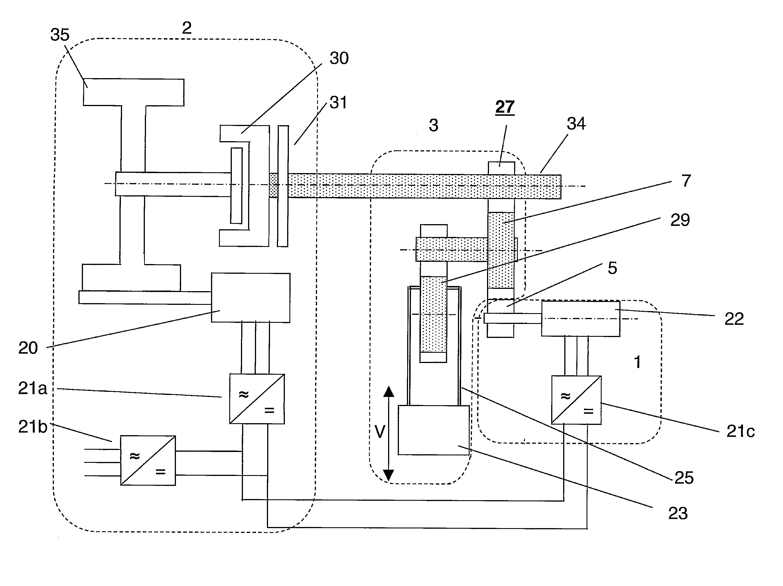
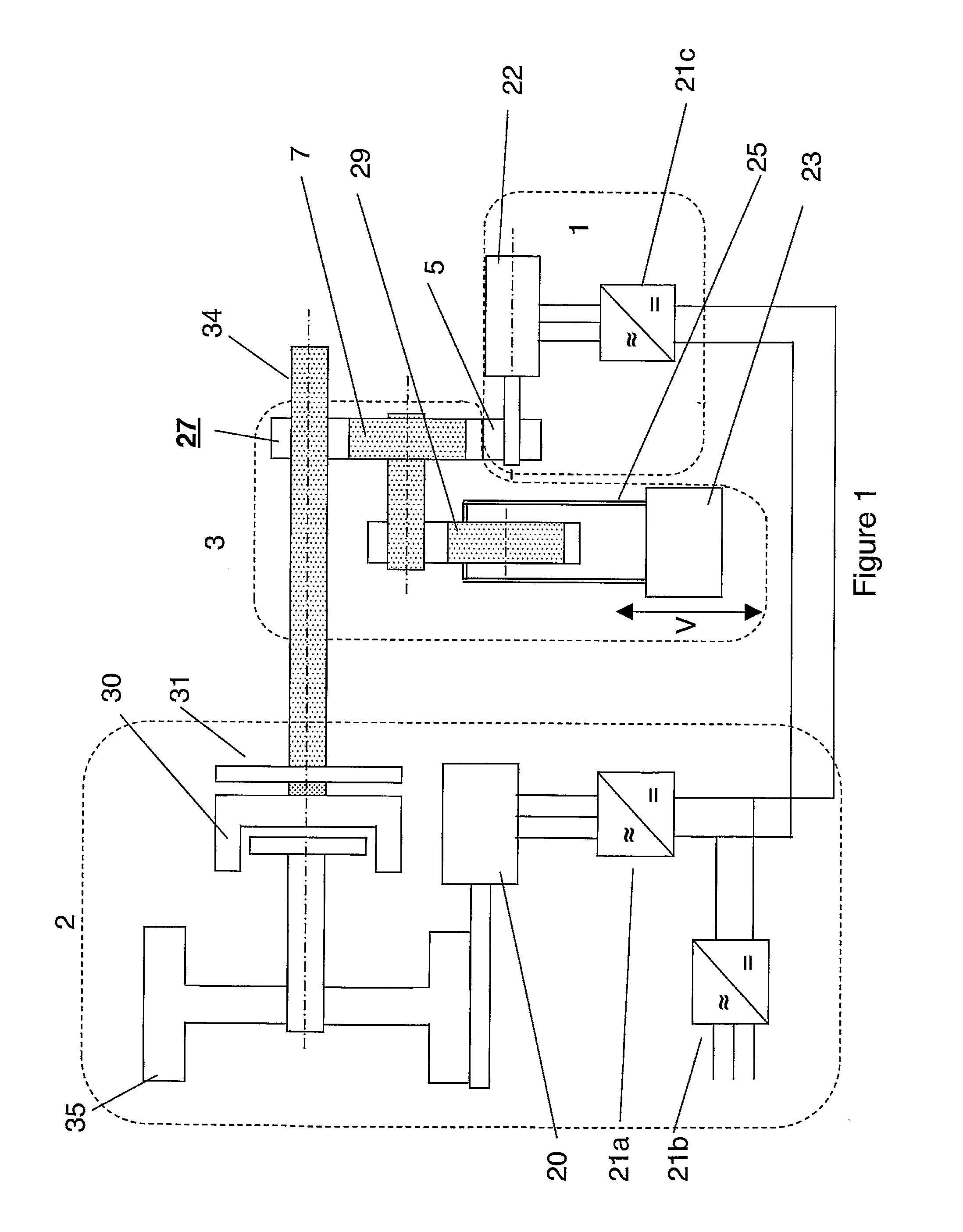
[0033]FIG. 1 shows the topology of a mechanical press with two drives: a mechanical drive 2 comprising a clutch 30 and flywheel 35, with associated motor 20, and a servo motor 22 with associated transmission 5. The figure also shows a press ram 23 which is driven in a reciprocal motion V by a main shaft 34 via press transmission gears 27 and an eccentric wheel 29 and to open and close the press.

[0034]With both drives, existing motor 20 and upgrade motor 22 in operation this is the topology of a hybrid servo press. With only the mechanical drive in place or operating, this would be a classic mechanical press. With only the motor upgrade Kit 1 operating, (and, possibly, an emergency brake), this would be a “full” servo press. However, the most likely topology for a mechanical press comprising the motor upgrade kit is the hybrid servo topology.

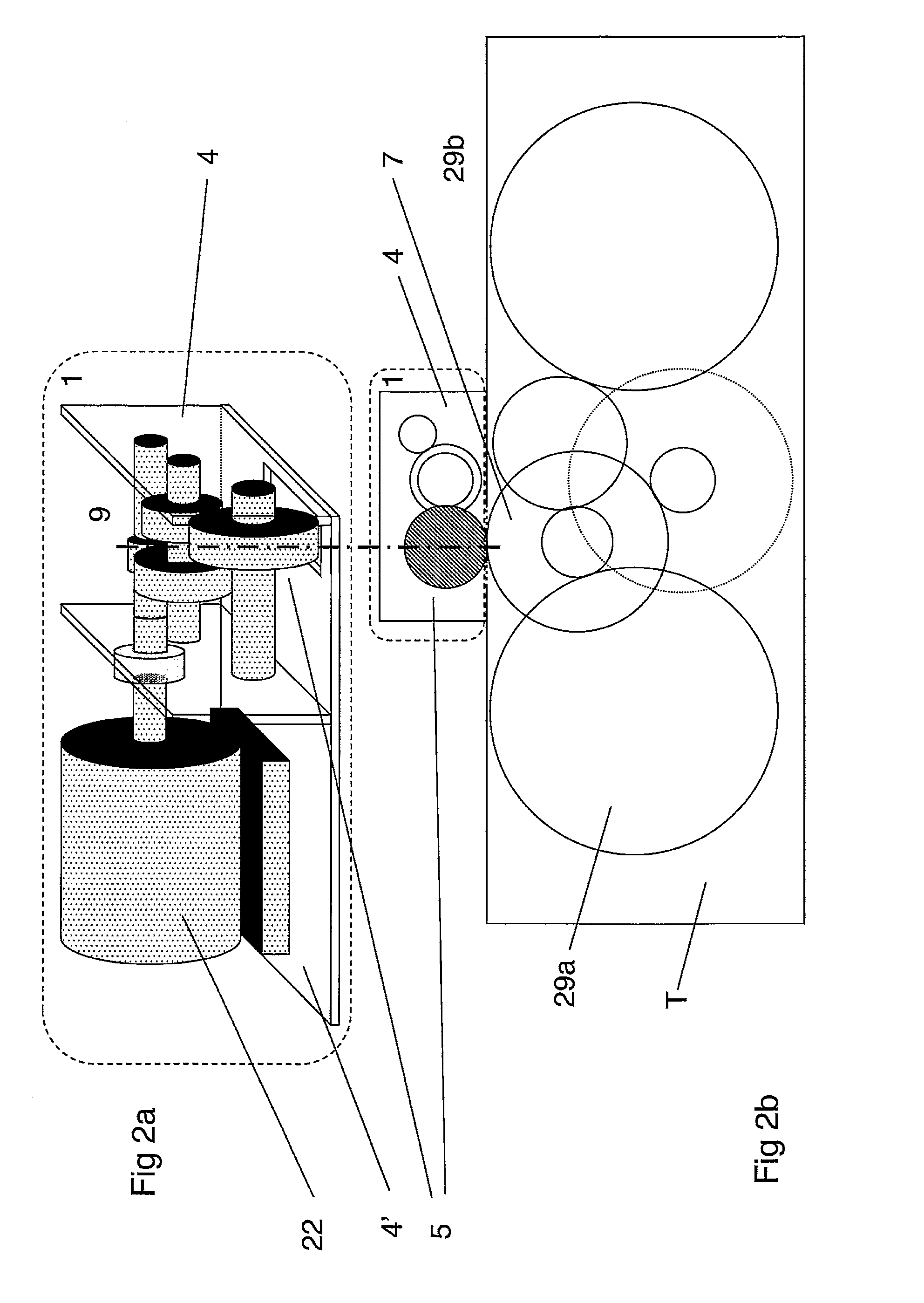
[0035]FIG. 2a shows a principle drawing of a kit 1 with a single motor, as well as a schematic diagram of how the kit would interact with the ge...


PUM

PropertyMeasurementUnit
life timeaaaaaaaaaa
timeaaaaaaaaaa
poweraaaaaaaaaa

Abstract

A press drive motor upgrade kit for adapting a mechanical press of the flywheel-driven type to a servo press including a drive motor and a drive train, and a mechanical press so modified. The kit includes at least one servo motor adapted for driving said mechanical press and a drive transmission apparatus or gear transmission or the like, connected to the servo motor and adapted for engagement with at least one gear or shaft of said drive train of said mechanical press. The kit may also include a baseplate or mounting structure on which the servo motor and transmission are arranged.

Description

TECHNICAL FIELD[0001]The invention concerns a conversion apparatus and method for a mechanical press. In particular it describes an electric motor upgrade kit of parts to adapt a mechanical press of the flywheel-driven type and convert it to a servo press. The kit may be advantageously used to convert an existing mechanical press, or a mechanical press being manufactured according to an existing traditional flywheel design, into a servo press, preferably of the hybrid servo type and thus provide greater control over a production cycle of the existing press or press made to a traditional design.TECHNICAL BACKGROUND[0002]Mechanical presses are commonly used to form industrial products such as automobile parts which are stamped or pressed from steel blanks or workpieces. Today's large mechanical presses are most often driven by a flywheel. The function of the flywheel is to store the necessary energy to carry out a pressing, stamping, punching etc operation. A motor drives the flywheel...

Claims


Application Information

Patent Timeline
Patent Type & Authority Applications(United States)
IPC IPC(8): B30B12/00B23P17/04
CPCB30B1/266Y10T29/49716B30B15/148B30B15/14B30B15/12B30B15/10B30B1/26
Inventor BOSGA, SJOERD
Owner ABB (SCHWEIZ) AG
Learn More