Nondestructive Device and Method for Evaluating Ultra-Hard Polycrystalline Constructions

a non-destructive, polycrystalline technology, applied in the direction of material analysis using wave/particle radiation, x/gamma/cosmic radiation measurement, instruments, etc., can solve the problems of affecting the economics of making parts, affecting the economics of parts, and the scope of destructive techniques is very limited, so as to achieve high vacuum requirements, reduce the effect of sampling time and small sampling chambers

Active Publication Date: 2010-04-15
SMITH INT INC
View PDF3 Cites 14 Cited by
  • Summary
  • Abstract
  • Description
  • Claims
  • Application Information

AI Technical Summary

Benefits of technology

[0014]A feature of the XRF device, systems and methods for using the same is that they provide a tool for obtaining qualitative and/or quantitative information relating to the material content and/or material microstructure in a desired region of a polycrystalline diamond construction in a manner that is not destructive and does not result in the unwanted waste of manufactured product, that has a consistent and high degree of accuracy, that relates to a greater extent of the construction material microstructure than previously obtainable by destructive method, and that is useful as a tool for troubleshooting

Problems solved by technology

While such destructive analysis and test methods are useful for providing useful certain information relating to the material properties of the sectioned region of the constriction, it is time consuming in that after the part is cut it must usually be further prepared by grinding, polishing or the like, then mounted for microscopic evaluation, and the microscopic evaluation must be taken over a number of different points to gather sufficient data to arrive at a numerical value, e.g.

Method used


Image

  • Nondestructive Device and Method for Evaluating Ultra-Hard Polycrystalline Constructions
  • Nondestructive Device and Method for Evaluating Ultra-Hard Polycrystalline Constructions
  • Nondestructive Device and Method for Evaluating Ultra-Hard Polycrystalline Constructions

Examples


Embodiment Construction

[0029]A nondestructive device and method useful for providing qualitative and / or quantitative information relating to the amount, location, and / or distribution of on or more particular target material within the material microstructure of an ultra-hard construction, e.g., an ultra-hard polycrystalline construction, according to the principles of this invention, is X-ray fluorescence (XRF). As described in better detail below, XRF is used to provide qualitative and / or quantitative information for a desired / targeted region of the ultra-hard polycrystalline construction in a manner that is accurate and that does not result in the destruction of the part.

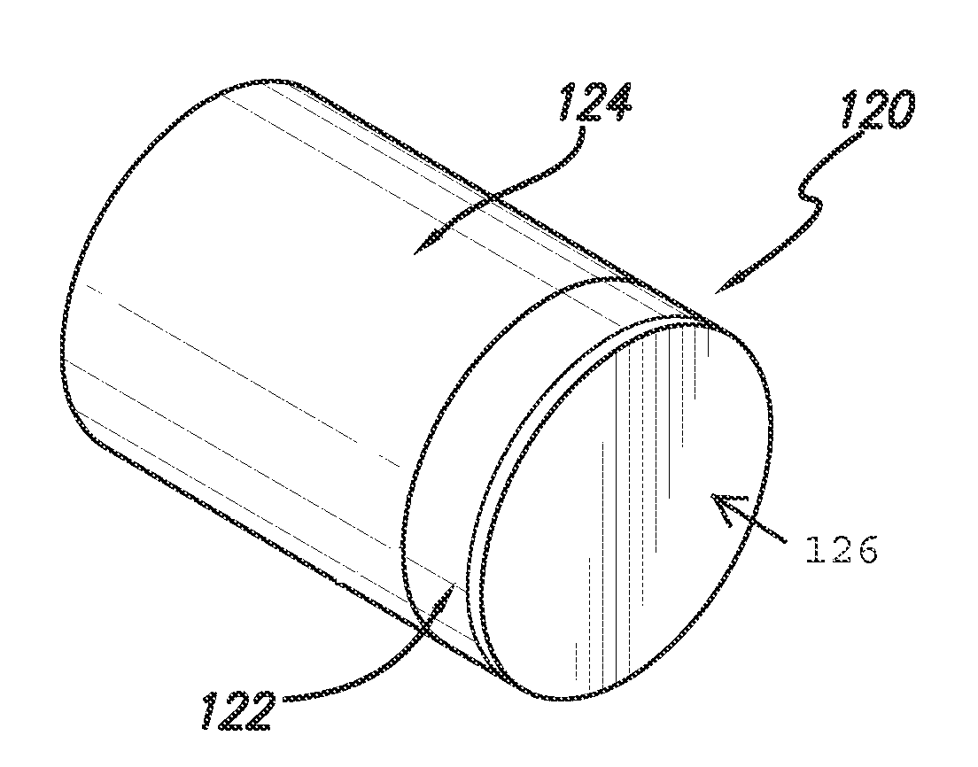
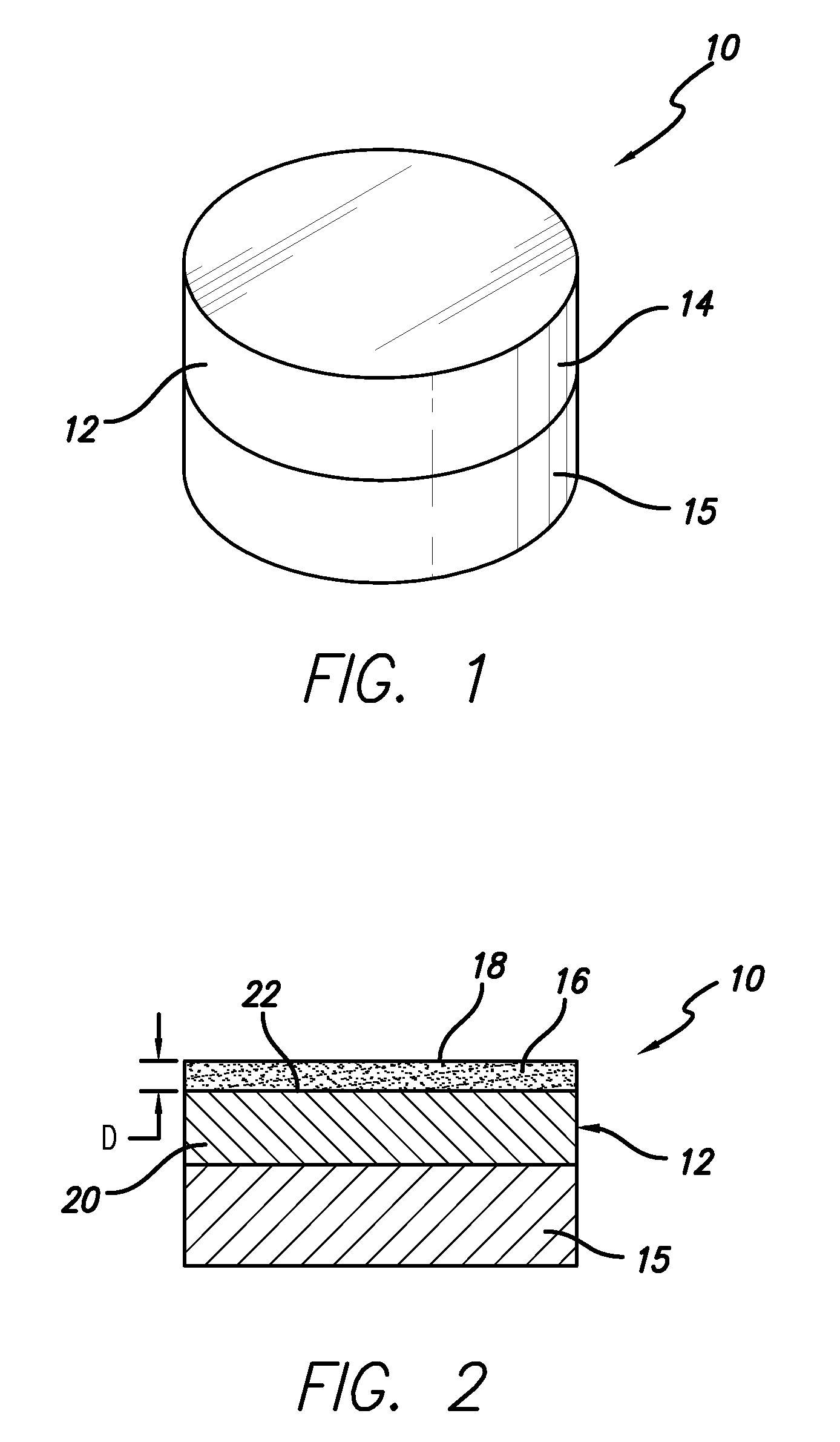
[0030]FIG. 1 illustrates an example ultra-hard construction 10. Ultra-hard constructions as described herein are understood to be those that include ultra-hard materials having a hardness of greater than about 4,000 kg / mm2. The construction comprises a body 12 formed from an ultra-hard polycrystalline material 14, e.g., that may compris...


PUM


Abstract

A device, system and method for nondestructively obtaining qualitative and/or quantitative information relating to the material properties of a region in a diamond body comprises directing x-rays onto the body. The body can comprise sintered or unsintered diamond. The body can ultimately be in the form of a cutting element used with a subterranean drill bit. The x-rays penetrate the body and cause a target element within the desired region including the same to emit x-ray fluorescence. The emitted x-ray fluorescence is received and information relating to content, location, and/or distribution of the target element in the region within the body is determined therefrom. The measured region can extend axially or radially from a surface of the body, and the target elements are nondiamond materials that can be constituents of a substrate attached to the body, or of a container used during HPHT sintering of the body.

Description

RELATION TO COPENDING PATENT APPLICATIONS[0001]This patent application is a continuation-in-part of U.S. patent application Ser. No. 11 / 550,671 filed on Oct. 18, 2006, that claims priority of U.S. Provisional Patent Application Ser. No. 60 / 728,057, that was filed on Oct. 18, 2005, and which are both incorporated herein in their entirety by reference.FIELD OF THE INVENTION[0002]This invention relates to nondestructive devices and methods useful for determining the material content and microstructure of a polycrystalline construction and, more specifically, to using X-ray fluorescence as a technique for providing quantitative and / or qualitative information relating to one or more target materials within one or more selected regions of an ultra-hard polycrystalline construction to thereby provide an indication of the material content and / or material microstructure of the construction and its suitability for a particular end-use application.BACKGROUND OF THE INVENTION[0003]Ultra-hard co...

Claims


Application Information

Patent Timeline
IPC IPC(8): G01N23/223G01T1/36E21B10/46E21B10/567
CPCE21B10/567G01N23/223G01N2223/076G01T1/00G01N2223/652
Inventor CORBETT, LOELEYRE, RONALD K.
Owner SMITH INT INC
Why Eureka
Try Eureka