
Nanomaterial-based gas sensors

a nanomaterial and gas sensor technology, applied in the field of gas sensors, can solve the problems of low selectivity, less-than-ideal sensitivity, and low sensitivity of bare nanomaterial-based sensors to certain gases

Inactive Publication Date: 2010-04-15
RGT UNIV OF CALIFORNIA
View PDF9 Cites 101 Cited by
  • Summary
  • Abstract
  • Description
  • Claims
  • Application Information

AI Technical Summary

Benefits of technology

[0014]The preferred embodiments of the presently-disclosed nanomaterial-based gas sensors and methods for producing nanomaterial-based gas sensors have several features, no single one of which is solely responsible for their desirable attributes. Without limiting the scope of these gas sensors and methods as defined by the claims that follow, their more prominent features will now be discussed briefly. After considering this discussion, and particularly after reading the section of this specification entitled “Detailed Description of the Preferred Embodiments,” one will understand how the features of the various embodiments disclosed herein provide a number of advantages over the current state of the art. These advantages include, without limitation, simplified and more efficient methods of fabricating functionalized nanomaterial-based gas sensors having outstanding sensing properties, including high sensitivity, low detection limits, fast response and recovery times, good reproducibility, good selectivity in the detection of gases, and long term stability within a wide temperature range.

Problems solved by technology

However, bare nanomaterial-based sensors do not exhibit high sensitivity toward certain gases due to their low absorption capacity.
This less-than-ideal sensitivity, as well as relatively low selectivity, has limited the use of nanomaterial-based gas sensors in practical applications.
In addition, functionalization of the sensors requires long fabrication time and complicated fabrication steps, which makes the process complex and costly.
These functionalization techniques also have limited spatial resolution, which makes the creation of high density sensor arrays difficult.
However, the number of analytes that can be detected by pristine CNTs is limited to only a few types, such as CO and hydrogen.

Method used


Image

  • Nanomaterial-based gas sensors
  • Nanomaterial-based gas sensors
  • Nanomaterial-based gas sensors

Examples


Embodiment Construction

,” one will understand how the features of the various embodiments disclosed herein provide a number of advantages over the current state of the art. These advantages include, without limitation, simplified and more efficient methods of fabricating functionalized nanomaterial-based gas sensors having outstanding sensing properties, including high sensitivity, low detection limits, fast response and recovery times, good reproducibility, good selectivity in the detection of gases, and long term stability within a wide temperature range.

[0015]Another advantage of the presently-disclosed gas sensors is the elimination of the relative humidity effect on CNT sensors and functionalized CNT sensors, thereby eliminating (or at least minimizing) the need to compensate for the RH effect under varying RH conditions.

[0016]Broadly, this disclosure, in one aspect, relates to a gas sensing device comprising a substrate layer having at least a pair of conductive (e.g., metallic) electrodes formed th...


PUM

PropertyMeasurementUnit
concentrationaaaaaaaaaa
RHaaaaaaaaaa
thicknessaaaaaaaaaa

Abstract

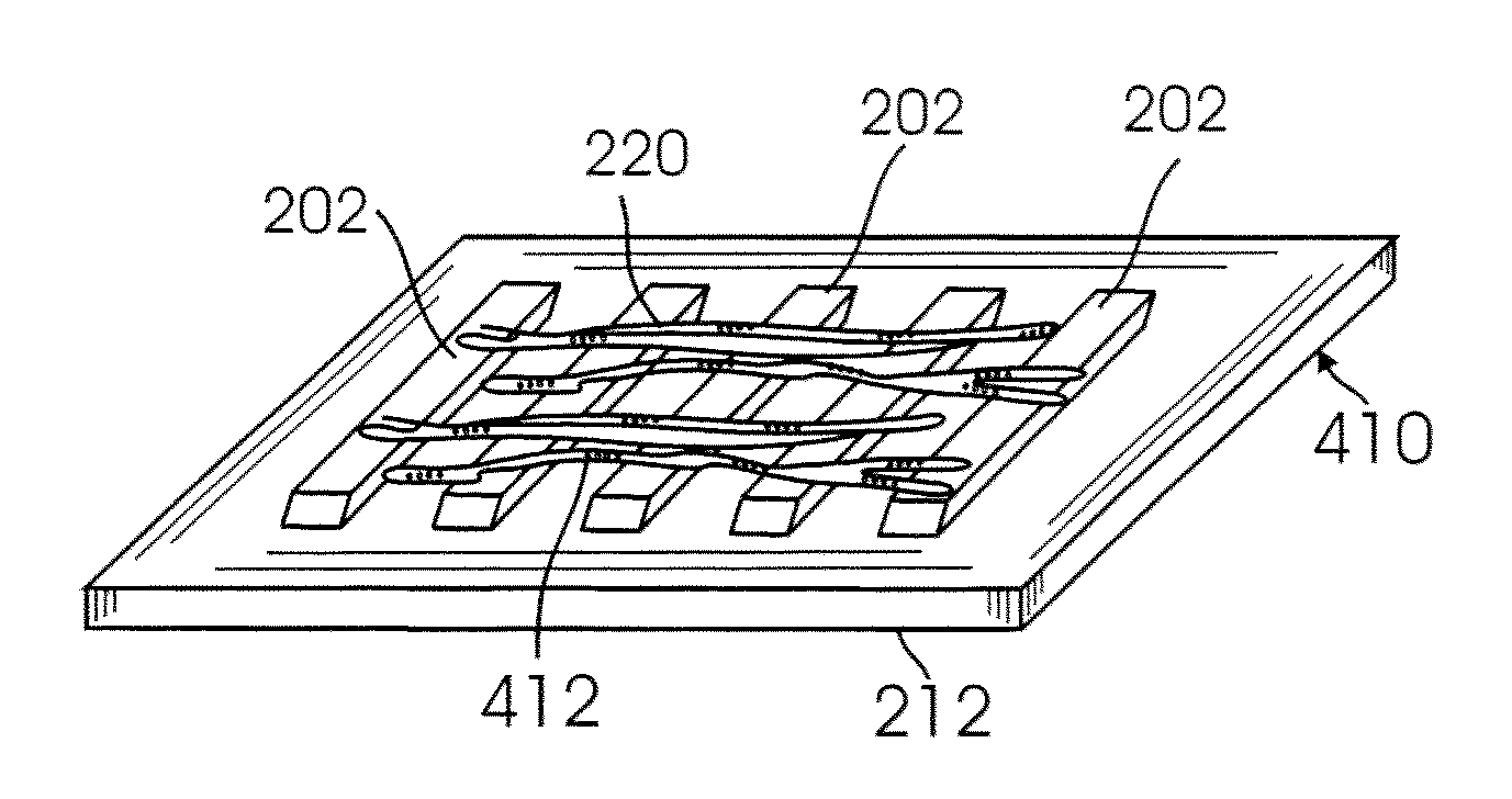
A gas sensing device (nanosensor) includes a substrate with at least a pair of conductive electrodes spaced apart by a gap, and an electrochemically functionalized semiconductive nanomaterial bridging the gap between the electrodes to form a nanostructure network. The nanomaterial may be single-walled carbon nanotubes (SWNTs) functionalized by the deposition of nanoparticles selected from the group consisting of an elemental metal (e.g., gold or palladium), a doped polymer (e.g., camphor-sulfonic acid doped polyaniline), and a metal oxide (e.g. tin oxide). Depending on the nanoparticles employed in the functionalization, the nanosensor may be used to detect a selected gas, such as hydrogen, mercury vapor, hydrogen sulfide, nitrogen dioxide, methane, water vapor, and / or ammonia, in a gaseous environment.

Description

CROSS-REFERENCE TO RELATED APPLICATIONS[0001]This application claims the benefit, under 35 U.S.C. §119(e), of co-pending U.S. provisional application Ser. No. 60 / 910,434, filed Apr. 5, 2007, and co-pending U.S. provisional application Ser. No. 60 / 865,218, filed Nov. 10, 2006, the disclosures of which are incorporated herein by reference in their entireties.FEDERALLY SPONSORED RESEARCH OR DEVELOPMENT[0002]Not ApplicableBACKGROUND OF THE INVENTION[0003]1. Field of the Invention[0004]The present invention relates to gas sensors, and more particularly, to electrochemically functionalized, nanomaterial-based gas sensors.[0005]2. Description of Related Art[0006]Gas detection instruments or gas sensors have a wide range of applications, including industrial health and safety, environmental monitoring, and process control. Some of the fields in which gas sensors are used include chemical refining, petroleum refining, rocket fuel production, fuel cell manufacturing, semiconductor processing,...

Claims


Application Information

Patent Timeline
Patent Type & Authority Applications(United States)
IPC IPC(8): G01N27/26C25D5/02G01N27/30
CPCY10T29/49Y10T29/49002G01N27/127
Inventor DESHUSSES, MARC A.MYUNG, NOSANG V.BOSZE, WAYNE
Owner RGT UNIV OF CALIFORNIA
Learn More