Metal containers

a technology of metal containers and containers, applied in the field of metal containers, can solve the problems of reducing the adhesion of metal containers, and reducing the risk of corrosion, so as to improve the adhesion, improve the adhesion, and simplify the manufacturing process

Inactive Publication Date: 2010-04-15
CROWN PACKAGING TECH
View PDF6 Cites 12 Cited by
  • Summary
  • Abstract
  • Description
  • Claims
  • Application Information

AI Technical Summary

Benefits of technology

[0013]a protective lacquer film applied to coat the entirety of the cut edge and all or part of the inward facing surfaces of both the container / component part and that part of the cover element which lies radially inward of the cut edge, thereby inhibiting corrosion of the cut edge;
[0025]Preferably, the protective lacquer film is applied by spraying onto the inward-facing surface of the container / component part after the cover element has been sealed onto the container / component part. Spray-application of the lacquer provides the benefits of ensuring complete coverage of lacquer film about the cut edge at minimal cost. Spray application has been found to reduce the risk of voids / air gaps forming between the lacquer film and the cut edge, as occurs with U.S. Pat. No. 3,339,788 A. Avoiding such voids / air gaps and ensuring direct contact between the lacquer film and the cut edge reduces the risk of corrosion to the bare metal of the cut edge prior to removal of the cover element. Further, by maximising the area of lacquer film in contact with the cover element, on removal of the cover element there is a reduced risk of the lacquer film completely detaching from the cover element, rather than tearing cleanly around the cut edge of the aperture.

Problems solved by technology

The bare metal of the cut-edge is therefore vulnerable to corrosion.
Such corrosion is particularly undesirable in the packaging of foodstuffs because it can cause contamination of the foodstuff.
The risk of corrosion is particularly prevalent for liquid foodstuffs or foodstuffs having a high moisture content.
The requirement for so many varied manufacturing operations increases the complexity in manufacture, as well as the cost of manufacture.
Manufacture of PVC can release toxic effluents during its manufacture, such as dioxin.
Consequently, the use of plastisols has disadvantages for health & safety and environmental reasons.
However, the peeling force applied by the consumer has to be large enough not only to break the bond between the upper patch and the can end, but also the bond between the lower patch and the can end.
This construction is also very complex—requiring two separate patches of aluminium foil (or similar metal) bonded to both the upper and lower faces of the can end via a multi-layered structure of adhesive and polymer layers.
Additionally, embossing the upper patch into the aperture can leave voids between the cut edge and the upper patch (as best shown in FIGS. 1 & 2 of U.S. Pat. No. 3,355,059), with the consequent risk of oxidation of the exposed metal of the cut edge.
However, although EP 0059635 B is directed at the same problem as the present invention, it requires accurate placement of the separate layers of thermoplastic resin that form the grommet / sleeve in order to ensure that the cut edge is adequately coated and protected, thereby increasing the costs and complexity of the manufacturing process of the can end.
As a consequence, the edge of the cover element is vulnerable to being caught on foreign objects (e.g. other containers) and thereby damaged.
The presence of this void / air gap results in the risk of corrosion on the bare metal of the cut edge if there is any moisture present within the void / air gap.
Generally, self-adhesive covering tapes are not suitable for use in retort processing, with the environmental conditions of retort processing (i.e. temperatures in excess of 100° C. and high humidity) causing the adhesive of the covering tape to become detached from the can end.

Method used


Image

  • Metal containers
  • Metal containers
  • Metal containers

Examples


Embodiment Construction

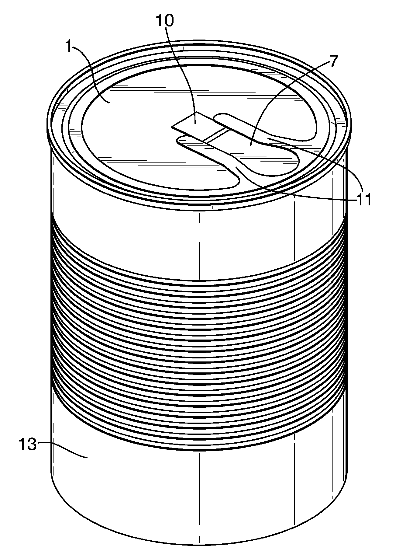
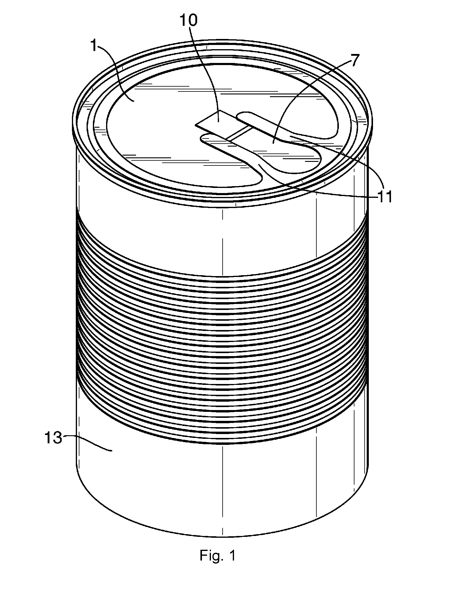
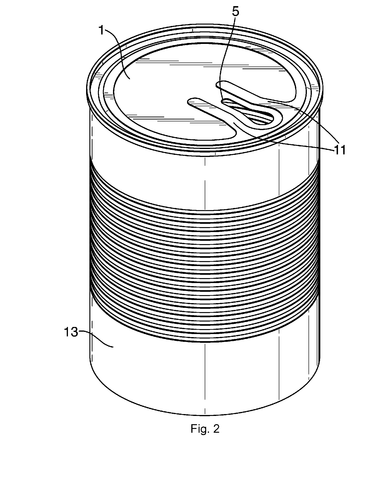
[0042]As illustrated in FIGS. 4, 5 and 6, a can end 1 is formed from a sheet of metal comprising a metal substrate 2 pre-coated with a heat sealable coating 3 containing polypropylene on the outward-facing surface of the metal substrate. An epoxy-based protective coating 4 is provided on the inward-facing surface of the metal substrate 2, the epoxy being a good inhibitor of corrosion. In the embodiment described, the metal substrate 2 is steel plate of 0.17 mm gauge. A dispensing aperture 5 is cut into the can end 1, thereby leaving the periphery of the aperture with a cut edge 6 of exposed bare metal (see FIG. 4). In the embodiment shown in the drawings, a cover element 7 is heat sealed to the outward-facing surface of the can end 1 to form a hermetic seal over the aperture 5. The cover element 7 has a foil metal substrate 8 of aluminium, the inward-facing surface of which includes a heat sealable coating 9 containing polypropylene. The cover element 7 also includes a tab portion 1...


PUM


Abstract

A metal container or component part of a metal container (e.g. a can end or sidewall of a can body) has an aperture defined by a cut edge about the periphery of the aperture, with a cover element sealed to the outward-facing surface of the can end so as to extend over and cover the aperture. A film of lacquer is directly applied (without the presence of an intermediate primer layer) to the inward-facing of the container / component part so as to coat the entirety of the cut edge and all or part of the inward-facing surfaces of both the can end and that part of the cover element located radially inward of the cut edge, thereby inhibiting corrosion of the cut edge. The invention is particularly suitable for can ends. The invention also relates to a method of making a can end to the invention.

Description

CROSS-REFERENCE TO RELATED APPLICATIONS[0001]This application is the National Stage of International Application No. PCT / EP2008 / 052207, filed Feb. 22, 2008, which claims the benefit of GB Application No. 0704054.6, filed Mar. 2, 2007, the disclosures of which are incorporated herein by reference in their entirety.Technical Field[0002]The present invention relates to a metal container or a component part of a metal container (e.g. can end or sidewall of a can body), the container or component part containing an aperture with a cut edge, adapted to be closed by a separate cover element. The container or component part is adapted to inhibit corrosion to the cut edge.[0003]Without limiting the generality of the present invention, the component part may, for example, be a can end for a container and / or may be a sidewall of a container. Further, the aperture may be for the dispensing of a product from the container and / or may be a venting or vacuum release feature.BACKGROUND ART [0004]In ...

Claims


Application Information

Patent Timeline
Patent Type & Authority Applications(United States)
IPC IPC(8): B65D17/50B05D7/22B21D51/40B21D51/46
CPCB65D2517/5008B65D17/502
Inventor ROWLAND, MARK JEREMYDUPUIS, MATTHIEU JACQUES
Owner CROWN PACKAGING TECH
Why Eureka
Try Eureka