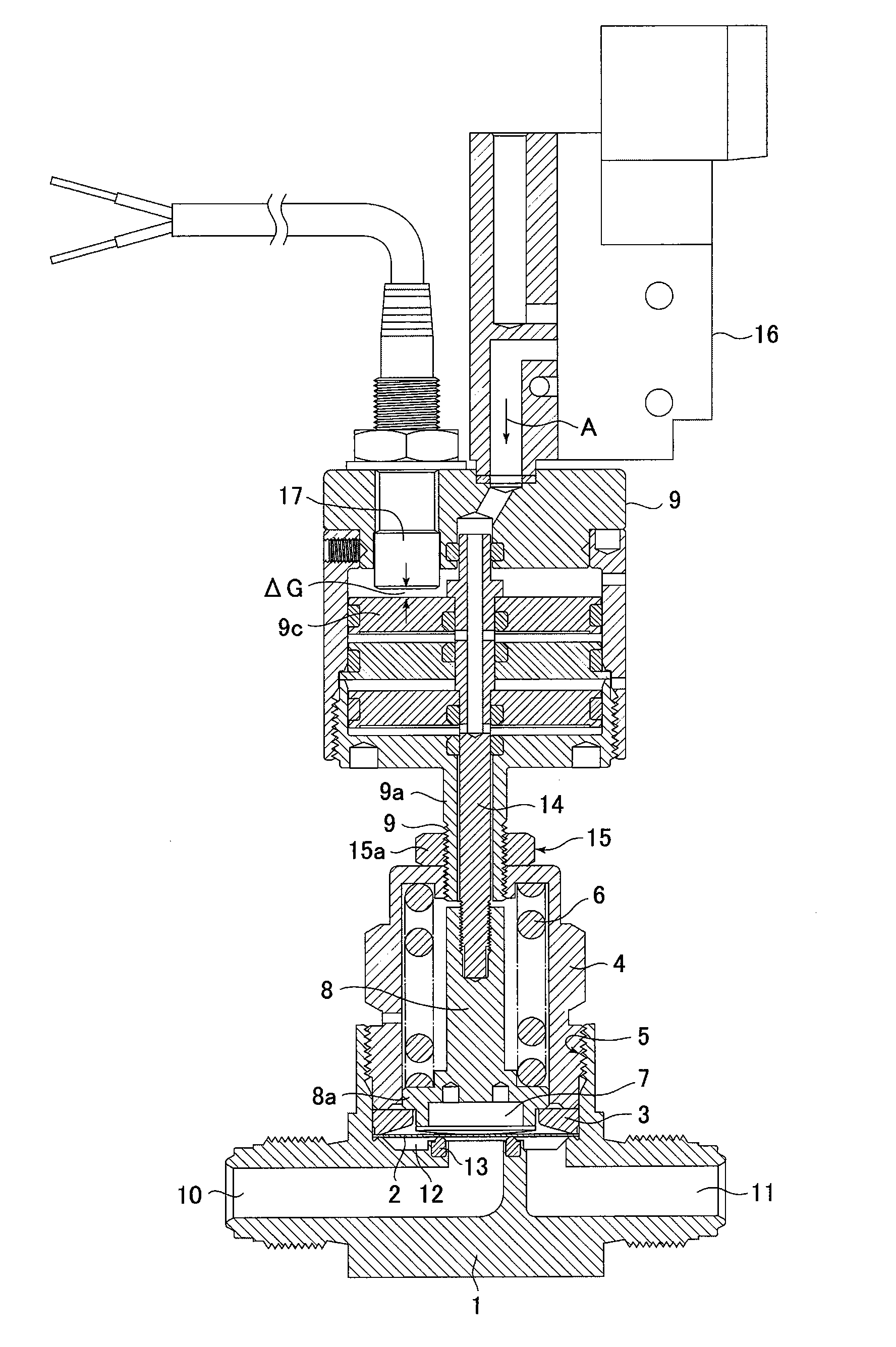
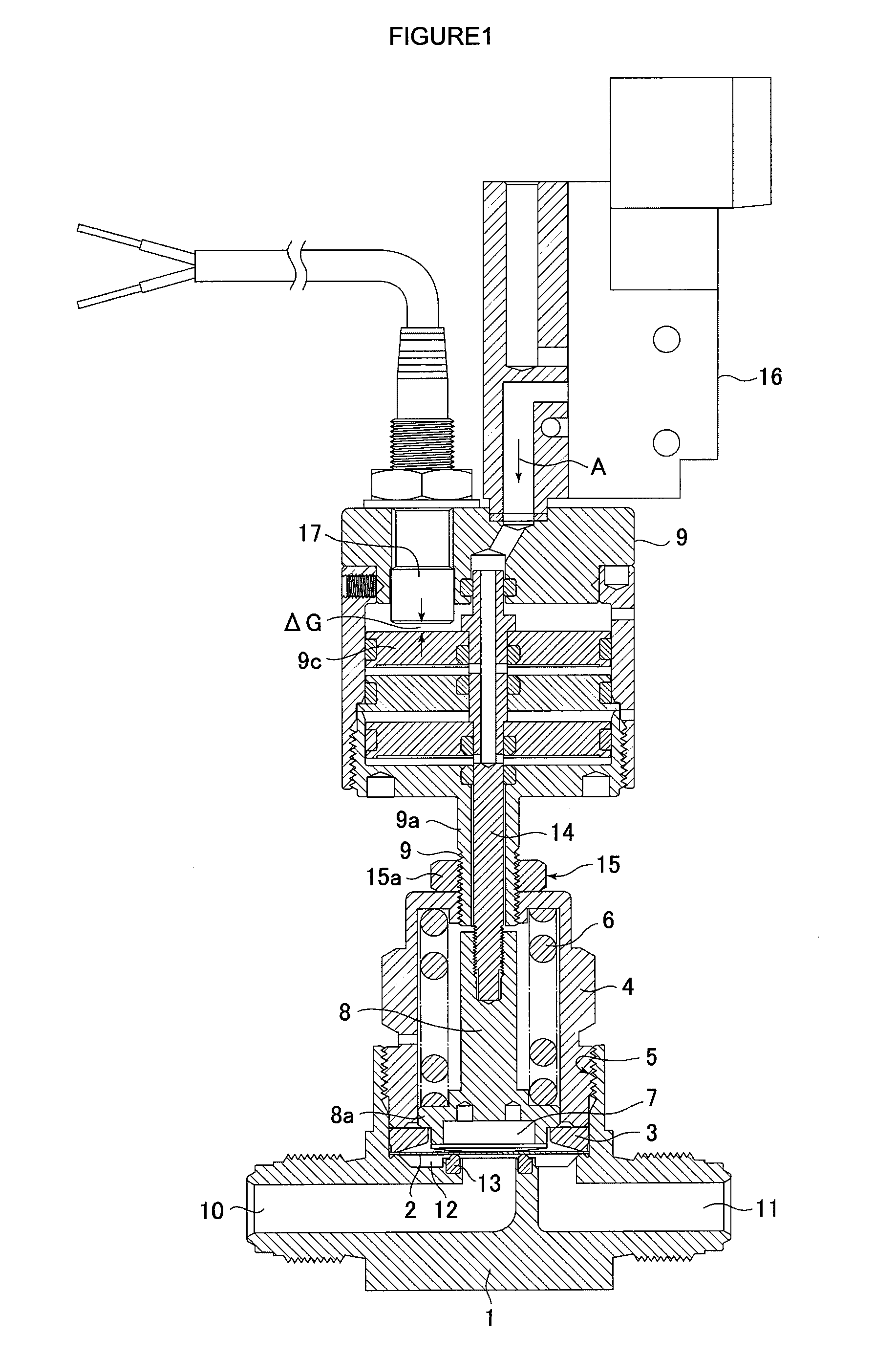
Direct touch type metal diaphragm valve
a metal diaphragm valve, direct touch technology, applied in the direction of diaphragm valves, engine diaphragms, operating means/releasing devices of valves, etc., can solve the problems of metal diaphragm cracks, metal diaphragm elastic deformation volume has its own limitation, etc., to achieve the effect of reducing the change of valve seat time and ensuring the flow rate coefficient cv
- Summary
- Abstract
- Description
- Claims
- Application Information
AI Technical Summary
Benefits of technology
Problems solved by technology
Method used
Image
Examples
embodiment 1
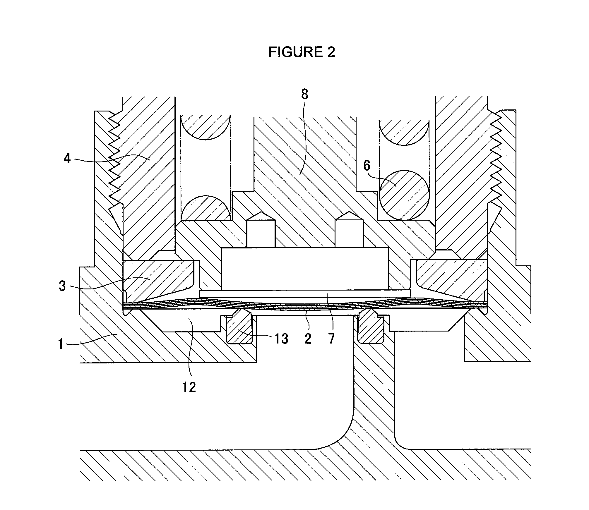
[0085]Referring to FIG. 2, FIG. 2 is a partially enlarged view to show the closed state of the valve for which the metal diaphragm 2 in the afore-mentioned implementation example 1 is used. FIG. 3 is a partially enlarged view to show the open state of the valve for which the metal diaphragm 2 in the afore-mentioned implementation example 1 is used. In accordance with FIG. 2 and FIG. 3, the valve stroke ΔS is chosen to be 1.5 mm. The metal diaphragm 2 is completely restored to its original shape due to the fact that the valve stroke ΔS is larger than the maximum height Δh=1.2 mm of a bulged part of the metal diaphragm 2.
embodiment 2
[0086]FIG. 4 and FIG. 5 are partly enlarged views to show a closed state (FIG. 4) and an open state (FIG. 5) when the valve stroke ΔS is made to be 0.7 mm in accordance with the valve shown in FIG. 1, in which the diaphragm 2 in the implementation example 1 mentioned in paragraph [0041] is used. The metal diaphragm 2 remains slightly deformed without being restored completely back to its original state, as shown in FIG. 3, even when the valve is closed. Specifically, when the valve stroke ΔS is made to be small, deformation volume of the metal diaphragm 2 becomes small; hence, distortion stress applied to the metal diaphragm 2 becomes relatively small.
[0087]Now, when comparing a valve stroke ΔS=1.5 mm with a valve stroke ΔS=0.7 mm, much difference is seen in the shape of a metal diaphragm 2 as stated before, but it is learned that not much difference is seen in the space G between a valve seat 3 and the inner surface of a metal diaphragm 2.
embodiment 3
[0088]FIG. 6 and FIG. 7 show the results of a Cv value obtained by the afore-mentioned equation (2) after the flow rate was measured by using the afore-mentioned Cv value measurement test device, shown in FIG. 8, on the metal diaphragm shown in FIG. 1 wherein the metal diaphragm 2 in the afore-mentioned implementation example 1 is used. Table 1 is a chart to show the lift, flow rate and Cv value corresponding to this test. The test was conducted under conditions of operating air pressure of 0.55 Mpa, and the projected height of the valve seat of 0.128 mm (the height after baking at 80° C.).
TABLE 1Lift(mm)Flow Rate (L / min)Cv Value0.0000.00.0000.1020.40.0030.20315.90.1300.31034.80.2840.40846.00.3750.50559.00.4820.59365.00.5310.70074.00.6040.79275.00.6120.89777.00.6281.00079.00.6451.10680.00.6531.20280.00.6531.31680.00.653
[0089]As apparent from FIG. 6 and FIG. 7, it is learned that a Cv value of 0.55 to 0.6 required for the valve can be achieved with a valve stroke ΔS of approximately ...
PUM
 Abstract
Description
Claims
Application Information
 - R&D
- Intellectual Property
- Life Sciences
- Materials
- Tech Scout
- Unparalleled Data Quality
- Higher Quality Content
- 60% Fewer Hallucinations
Browse by: Latest US Patents, China's latest patents, Technical Efficacy Thesaurus, Application Domain, Technology Topic, Popular Technical Reports.
© 2025 PatSnap. All rights reserved.Legal|Privacy policy|Modern Slavery Act Transparency Statement|Sitemap|About US| Contact US: help@patsnap.com


