Optimized signal control in frequency-doubled laser sources

a frequency-doubled laser and signal control technology, applied in the field of semiconductor lasers, can solve the problems of not contributing directly to the creation of power, saving a significant amount of power consumption, and power consumption of a frequency-doubled laser system, so as to improve emission quality, stabilize emission, and optimize efficiency

Inactive Publication Date: 2010-04-22
CORNING INC
View PDF26 Cites 8 Cited by
  • Summary
  • Abstract
  • Description
  • Claims
  • Application Information

AI Technical Summary

Benefits of technology

[0003]The power consumption of a frequency doubled laser system can be the result of two or more different types of signals applied to the system. One type can be referred to generally as the gain control signal because it is applied to the gain control elements of the IR semiconductor laser. Additional types of control signals can be referred to generally as complementary control signals and are applied to complementary control elements of the laser. These complementary control signals can function in a variety of ways and can generally be used to optimize efficiency, stabilize emission, enhance emission quality, etc. For example, and not by way of limitation, one type of complementary control signal operates on the wavelength tuning mechanism of the semiconductor laser to control the emission wavelength of the semiconductor laser to keep the wavelength of the laser aligned with the phase matching wavelength of the PPLN crystal or other SHG device as the temperature of the system drifts over time. Another type of complementary control signal operates on the phase section of the semiconductor laser and can be used to send high frequency signals to the phase section of the laser in order to randomize the laser mode selection or to control the phase section is some other manner to optimize emission. In addition, it is contemplated that the complementary control signal may be used to cooperate with an optical alignment mechanism to control optical coupling between the semiconductor laser and the SHG device and compensate for thermal or mechanical misalignment. It is also contemplated that the complementary control signal can be utilized to control a temperature control mechanism of the semiconductor laser to optimize emission.
[0004]The present inventors have recognized that, although these and other types of complementary control signals are needed the help enhance SHG conversion efficiency, optimize image quality, or maintain optimum coupling efficiency, they often do not contribute directly to create power. Accordingly, one object of the present disclosure is to provide schemes for minimizing the power dedicated to these complementary control signals.
[0005]In most laser projection systems, laser sources are often switched OFF over significant periods of time so the Gain signal applied to the pump laser comprises an alternating sequence of relatively high intensity active projection periods ModON and relatively low intensity inactive projection periods ModOFF. As there is no signal to be displayed during periods ModOFF, some of the complementary control signals can also be set to an inactive state QOFF. These complementary control signals are then made of a succession of active states QON and QOFF that are synchronized with ModON and ModOFF periods and therefore saves a significant amount of power consumption.

Problems solved by technology

The power consumption of a frequency doubled laser system can be the result of two or more different types of signals applied to the system.
The present inventors have recognized that, although these and other types of complementary control signals are needed the help enhance SHG conversion efficiency, optimize image quality, or maintain optimum coupling efficiency, they often do not contribute directly to create power.
These complementary control signals are then made of a succession of active states QON and QOFF that are synchronized with ModON and ModOFF periods and therefore saves a significant amount of power consumption.

Method used


Image

  • Optimized signal control in frequency-doubled laser sources
  • Optimized signal control in frequency-doubled laser sources
  • Optimized signal control in frequency-doubled laser sources

Examples


Embodiment Construction

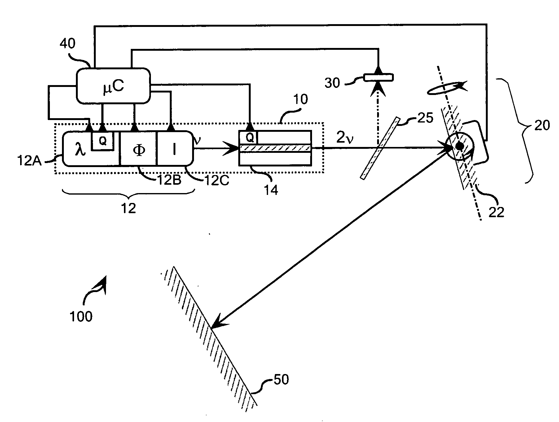
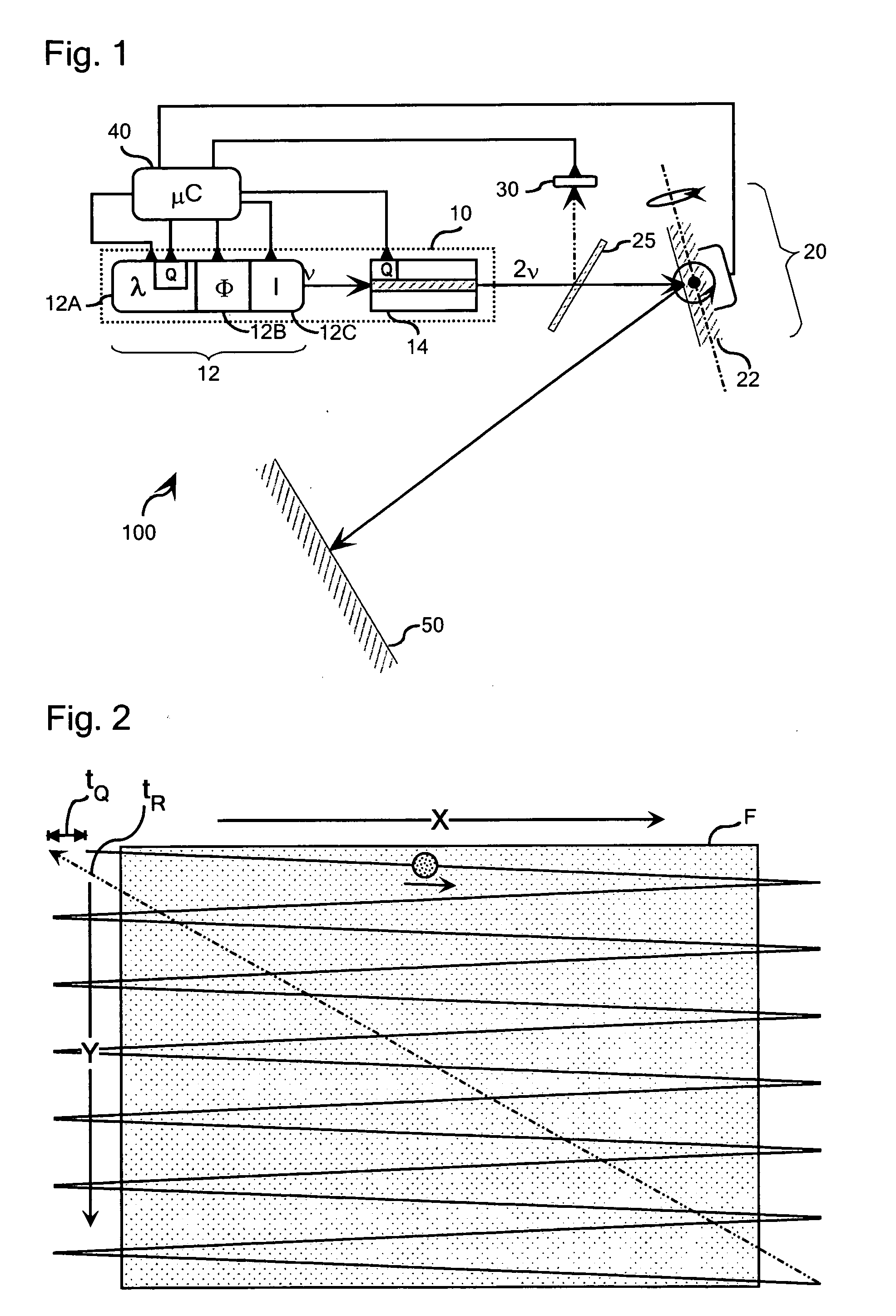
[0012]Referring initially to FIG. 1, the concepts of the present disclosure may be conveniently illustrated with general reference to a laser source 10 comprising a two or three-section DBR-type semiconductor laser 12, although the concepts of the present disclosure can be executed in the context of various types of semiconductor lasers, the design and operation of which is described generally above and is taught in readily available technical literature relating to the design and fabrication of semiconductor lasers. In the context of a frequency-doubled light source of the type illustrated in FIG. 1, the DBR laser 12 is optically coupled to a light wavelength conversion device 14. The DBR laser 12 illustrated schematically in FIG. 1 comprises a wavelength selective section 12A, a phase section 12B, and a gain section 12C. The light beam emitted by the semiconductor laser 12 can be either directly coupled into the waveguide of the wavelength conversion device 14 or can be coupled th...


PUM


Abstract

The present disclosure relates generally to semiconductor lasers and laser projection systems. According to one embodiment of the present disclosure, a method of operating a laser projection system is provided. According to the method, the laser projection system is utilized to display a sequence of pixelized image frames comprising an alternating sequence of relatively high intensity active projection periods ModON and relatively low intensity inactive projection periods ModOFF. A complementary control signal transitions between an active state QON during the relatively high intensity active projection periods ModON and an inactive state QOFF during the relatively low intensity inactive projection periods ModOFF. The transition of the complementary control signal from the inactive state QOFF to the active state QON is conditioned to anticipate initiation of relatively high intensity active projection periods ModON such that it is optimized upon initiation of the relatively high intensity active projection periods ModON. Additional embodiments are disclosed and claimed.

Description

BACKGROUND OF THE INVENTION[0001]The present disclosure relates generally to semiconductor lasers and, more particularly, to schemes for decreasing power consumption in frequency-doubled semiconductor laser sources.SUMMARY OF THE INVENTION[0002]The present disclosure relates generally to semiconductor lasers, which may be configured in a variety of ways. For example and by way of illustration, not limitation, short wavelength sources can be configured for high-speed modulation by combining a single-wavelength semiconductor laser, such as a distributed feedback (DFB) laser, a distributed Bragg reflector (DBR) laser, or a Fabry-Perot laser with a light wavelength conversion device, such as a second harmonic generation (SHG) crystal, e.g., MgO-doped periodically poled lithium niobate (PPLN). The SHG crystal can be configured to generate higher harmonic waves of the fundamental laser signal by tuning, for example, a 1060 nm DBR or DFB laser to the spectral center of a SHG crystal, which...

Claims


Application Information

Patent Timeline
Patent Type & Authority Applications(United States)
IPC IPC(8): H01S3/11H01S3/00H01S3/04
CPCH01S5/0092H01S5/06256H04N9/3188H01S5/0687H04N9/3129H01S5/06837
Inventor BHATIA, VIKRAMGOLLIER, JACQUESPIKULA, DRAGANRICKETTS, DANIEL OHEN
Owner CORNING INC
Why Eureka
Try Eureka