Resistance heater based air heating device

a technology of resistance heater and air heating device, which is applied in the direction of domestic stoves or ranges, combustion types, applications, etc., can solve the problems of inconvenience, low thermal conductivity, and inability to meet the needs of consumers, and achieve low thermal diffusivity, low thermal conductivity, and high surface area

Inactive Publication Date: 2010-05-13
COORSTEK INC
View PDF28 Cites 6 Cited by
  • Summary
  • Abstract
  • Description
  • Claims
  • Application Information

AI Technical Summary

Benefits of technology

[0007]The present invention features a heating device comprising an electric resistance heater that is disposed within a low thermal conductivity enclosure or an enclosure having low thermal diffusivity. In more particular embodiments, such an enclosure is configured so as to provide a high surface area which in combination with the heater heats the air passing through the enclosure. In more particular embodiments, such an enclosure is configured an...

Problems solved by technology

Stoves or furnaces for burning biomass fuel to produce energy are not new.
There are many stoves and furnaces for burning biomass fuel, however, there currently is not widespread acceptance of these furnaces or stoves by consumers.
On...

Method used


Image

  • Resistance heater based air heating device
  • Resistance heater based air heating device
  • Resistance heater based air heating device

Examples


Embodiment Construction

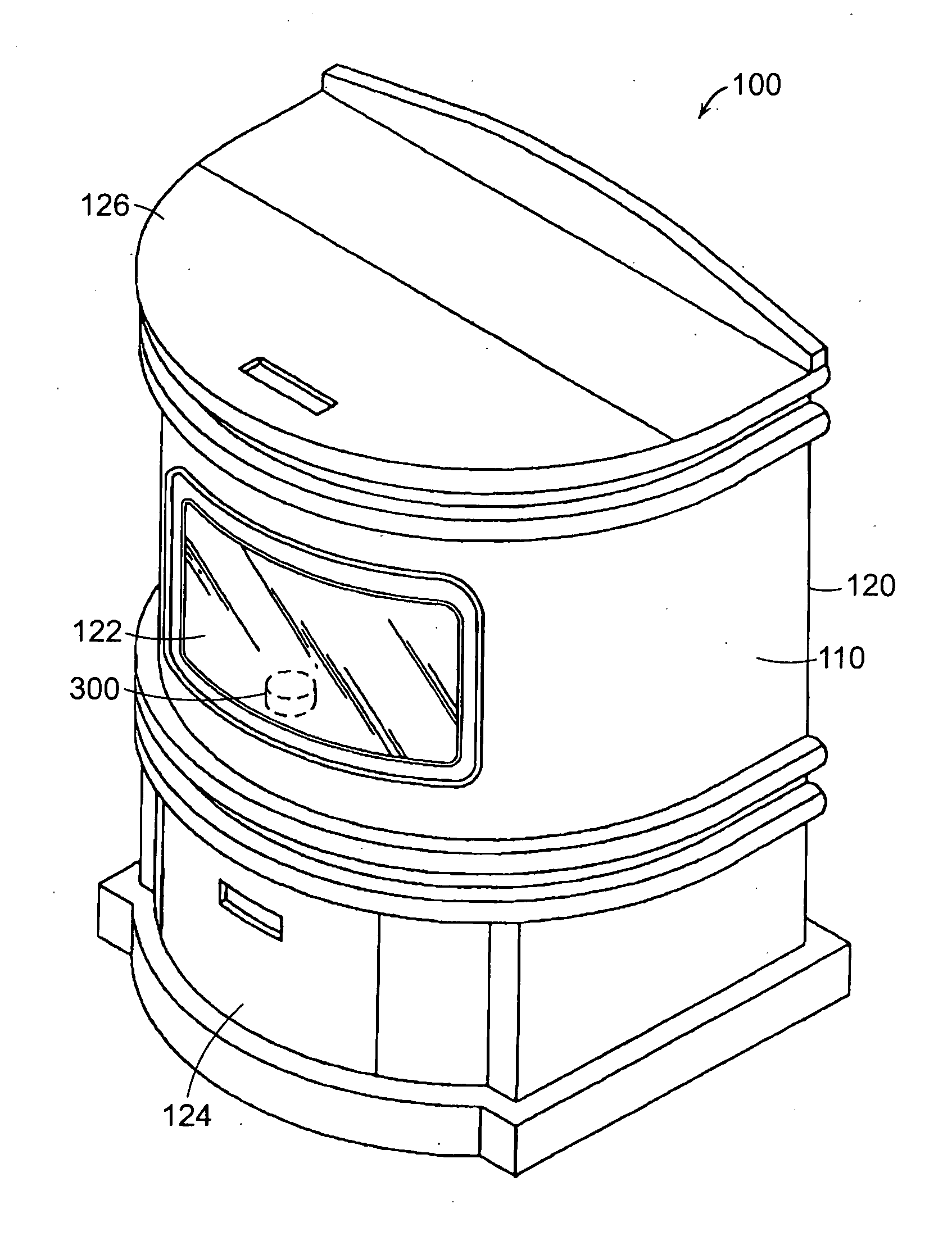
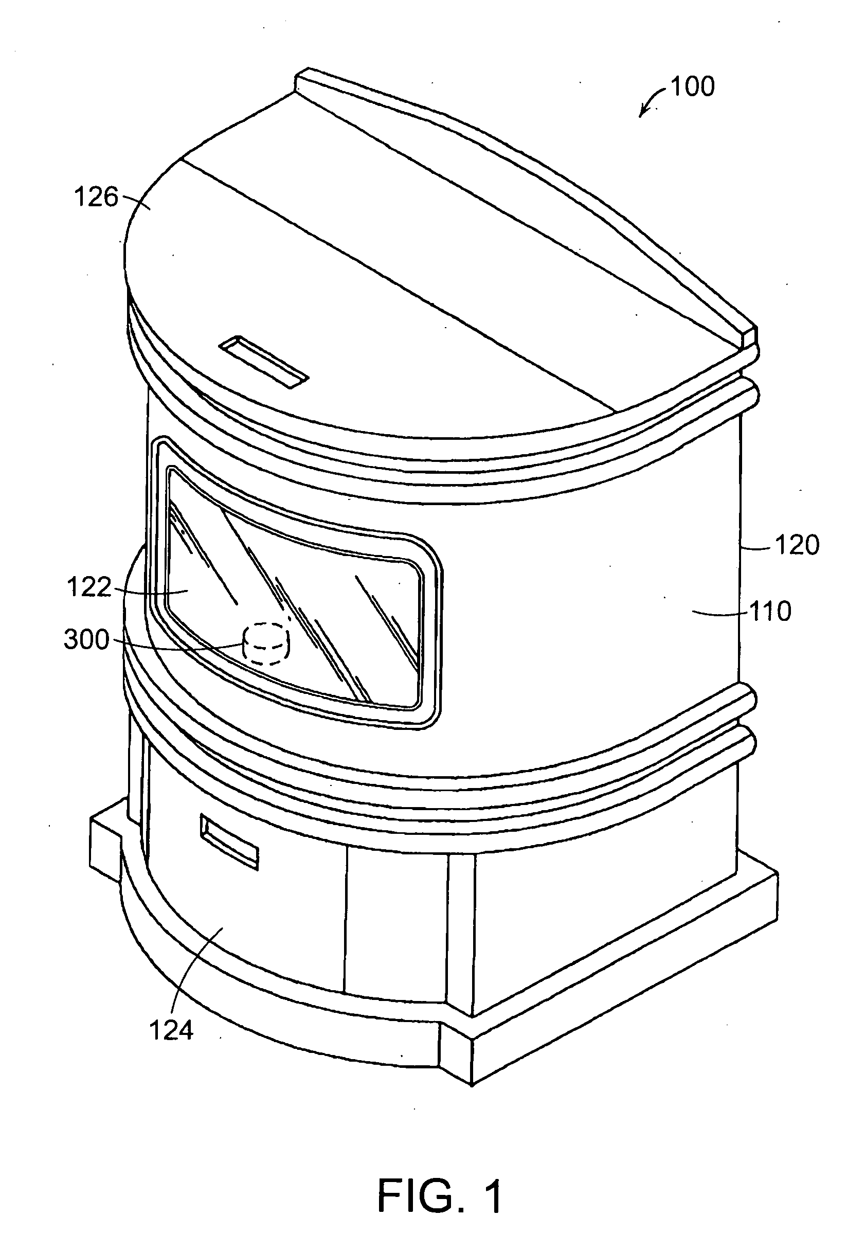
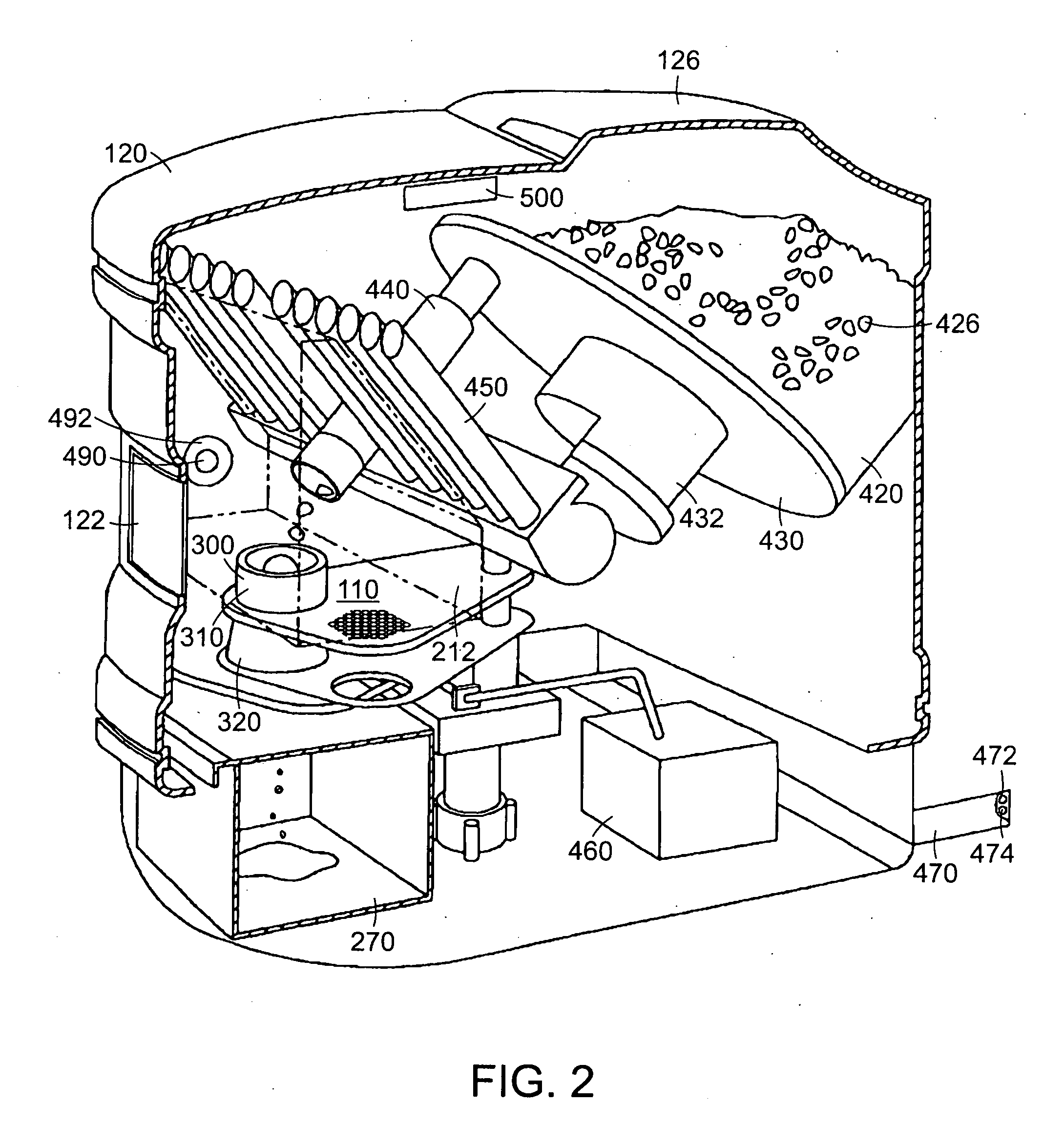
[0030]Referring now to the various figures of the drawing wherein like reference characters refer to like parts, there is shown in FIG. 1 an illustrative view an exemplary furnace 100 having a combustion chamber 110 in which is located a resistance heater air heating device 500 of the present invention. The furnace 100 includes a housing 120 and the combustion chamber 110 is within the housing 120. In the illustrated embodiment, at least a portion of the combustion chamber 110 a viewable through a window 122, which is sealed with respect to the housing 120. The housing 120 also includes an access panel 124 that allows access to a portion of the interior of the furnace 100 located below the combustion chamber. The access panel, in some embodiments, allows users to remove combustion products from the furnace 100. As shown more clearly in FIG. 4, the housing 120 also includes a hopper and a feed mechanism for controllably placing biomass combustibles into the combustion chamber 110. Th...


PUM


Abstract

Featured is a resistance heater air heating device that includes a low thermal conductivity enclosure and an electric resistance heater that is disposed within such an enclosure. In more particular embodiments, such an enclosure is configured so as to provide a high surface area which in combination with the heater heats the air passing through the enclosure. In more particular embodiments, the ceramic enclosure is configured and arranged so as to include a through aperture in which is disposed the electric resistance heater and through which the air flows along the length of the through aperture.

Description

[0001]This application claims the benefit of U.S. provisional application No. 61 / 192,641 filed Sep. 18, 2008, which is incorporated herein by reference in its entirety.FIELD OF INVENTION[0002]The present invention relates to devices and structures for igniting the biomass within a furnace and methods related thereto.BACKGROUND OF THE INVENTION[0003]Biomass is one of the oldest fuels known to man and is vegetation or fuel from plants, agricultural waste products or the like. During photosynthesis, plants combine carbon dioxide from the air and water from the ground to form carbohydrates that are the building blocks of biomass. Burning biomass efficiently extracts the energy stored in the chemical bonds and produces carbon dioxide and water. Generating energy and heat by burning biomass displaces more polluting forms of energy generation and also provides other environmental benefits, such as reducing acid rain, soil erosion, water pollution and pressure on landfills. Additional envir...

Claims


Application Information

Patent Timeline
IPC IPC(8): F23B90/00
CPCF23B50/12F23B90/02F23Q7/04F24B15/005
Inventor CHODACKI, THOMAS A.CASTRIOTTA, III, LOUISTANGUAY, MICHAEL W.
Owner COORSTEK INC
Why Eureka
Try Eureka