Cross-chirped interferometry system and method for light detection and ranging

a cross-chirped interferometry and light detection technology, applied in the field of interferometry for light detection and ranging, can solve the problems of large bandwidth and short pulse timing, inadequacies of high-precision sub-millimeter measurements, and lack of resolution capability

Active Publication Date: 2010-05-13
INSTITUT NATIONAL DE LA RECHERCHE SCIENTIFIQUE
View PDF8 Cites 32 Cited by
  • Summary
  • Abstract
  • Description
  • Claims
  • Application Information

AI Technical Summary

Benefits of technology

[0019]Other objects, advantages and features of the present invention will become more apparent upon reading of the following non-

Problems solved by technology

Due to the high speed of light, this technique is not appropriate for high precision sub-millimeter measurements [1, 2].
Use of a long pulse results in a lack of resolving capability as multiple reflectors may exist along the line-of-sight (LOS).
On the other hand, use of a large bandwidth and a short pulse timing to increase the resolution and the accuracy may be hazardous to the environment since maximum permissible exposure (MPE) regulation may be exceeded as high energy pulse laser is required to increase the sensitivity and accuracy for the signal detection.
Both interferometry techniques have critical limitations as far as the range and the repetition rate are concerned.
Only expensive high resolution and long range reflectometry using the OFDR has been found to reach performances up to 22 μm and 35 meters, respectively [3].
Failure of the dispersion matching results in a broadening of the virtual pulse autocorrelations.
In other words, dispersion causes the resolution degradation of the reflectometry system.
The finite spectrum resolution in detect

Method used


Image

  • Cross-chirped interferometry system and method for light detection and ranging
  • Cross-chirped interferometry system and method for light detection and ranging
  • Cross-chirped interferometry system and method for light detection and ranging

Examples


first embodiment

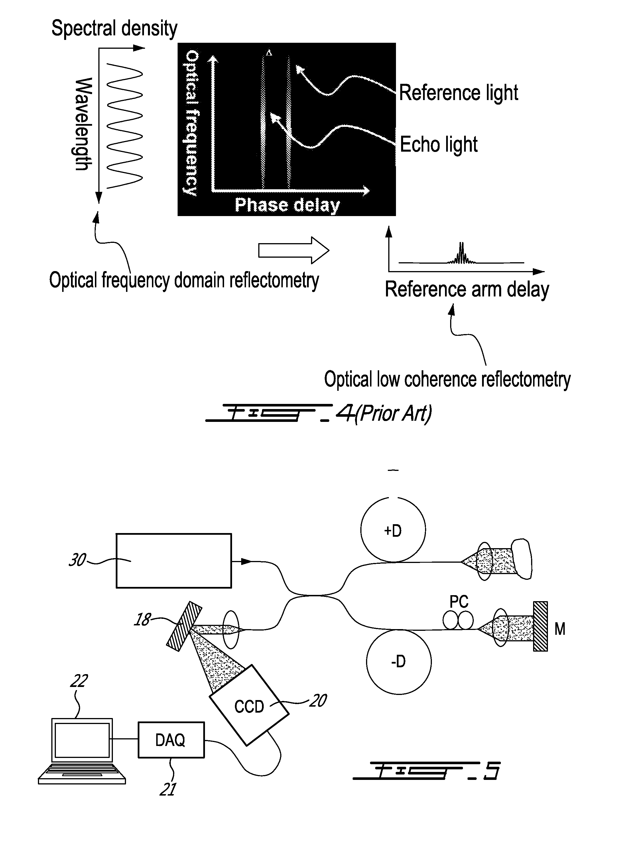
[0042]According to a system according to a first aspect of the present invention, there is provided a mid-range laser range finder based on cross-chirp interference (XCI).

[0043]In the system illustrated in FIG. 5 for example, the signal from the broadband source 30 is divided between the signal arm (+D) and the reference arm (−D). The optical delay in the reference arm can be varied by movement of the reference mirror (M). The broadband source 30 can be either continuous a wave (CW) or a pulsed wave.

[0044]The lights from the two interferometer arms are dispersed with signs. In an embodiment described hereinbelow in relation to FIG. 12, the lights from the two interferometer arms are dispersed with different amounts.

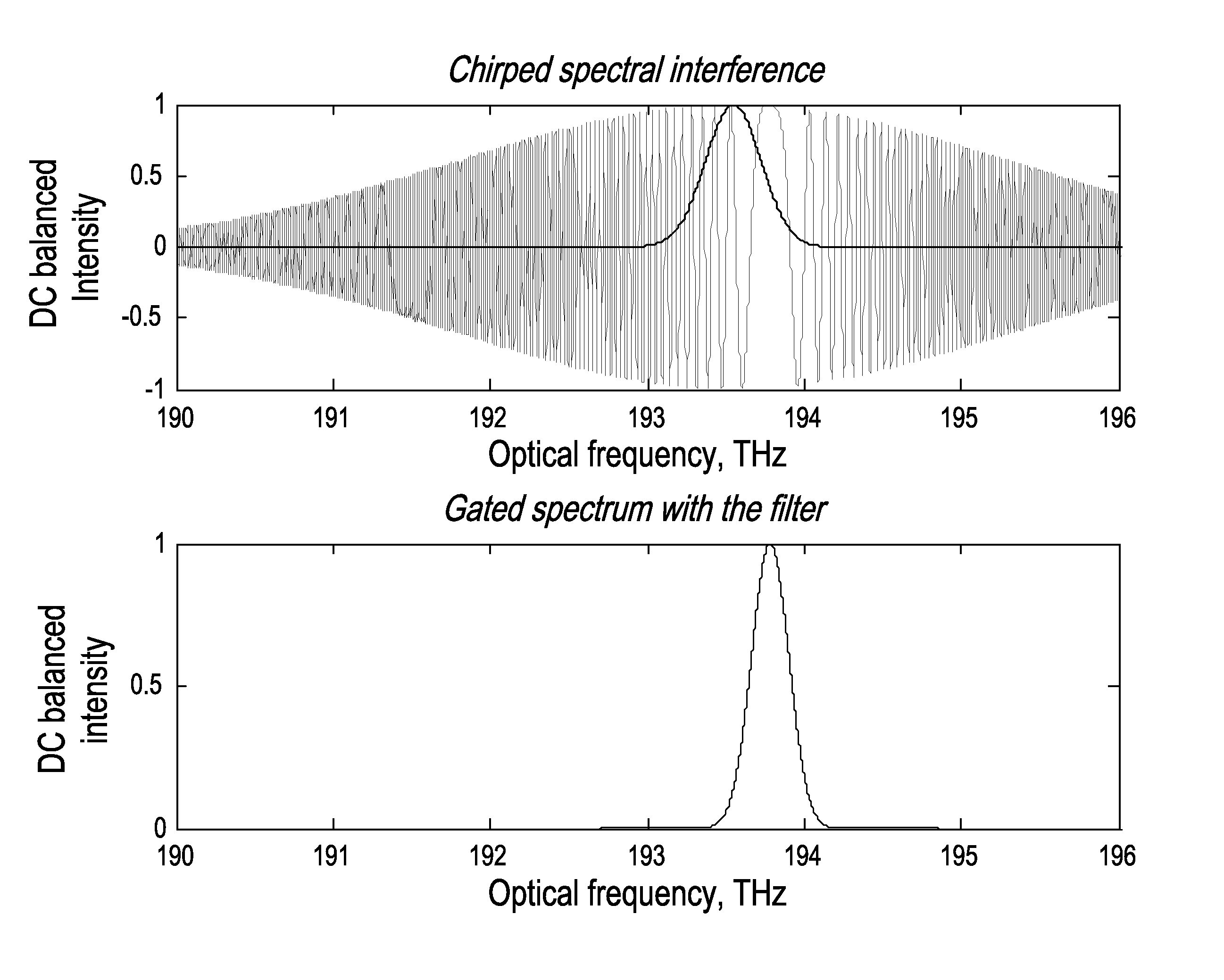
[0045]The phase gating associated with the relative phase delay between the reference and the signal arms is made in spectrally resolved detection when the two interfered beams, cross-chirped by unbalanced dispersions, are received in a spectrometer such as charged-couple...

second embodiment

[0060] there is provided a system for multiplying the detection range by the use of phase modulated multiple time-delays in the reference arm, as illustrated for example in FIG. 9.

[0061]The system illustrated in FIG. 9 is able to multiply the detection range by the use of phase modulated multiple time-delays in the reference arm. The source signal is divided between the signal arm (+D) and the reference arm (−D), and the reference arm (−D) is itself divided into a plurality of reference arms, each one having an optical delay varied by movement of a respective reference mirror (M). The source signal 30 is a wavelength swept laser, which generates a continuous wave with linear wavelength sweep in time. A fiber optic circulator 50 routes, on the one hand, the forward light wave to a fiber-optic 2×2 coupler 52 that is used to form the Michelson fiber-optic interferometer, and, on the other hand, the reflected (backward) light to the detector. Opposite signs of dispersion are applied to ...


PUM


Abstract

An interferometric method and system enabling light echoes-to-spectrum mapping, applicable for laser rangefinder, biomedical imaging including surface 3D mapping and tomography, vehicle position identification, and spectrum analysis. The direct mapping into spectrum allows a time-of-flight detection without using any timing pulse modulation. The sensitivity of the detection can be as high as that of the conventional low coherence interferometry, thereby an eye-safe and low-cost solution not compromising performance. In a practical implementation, high accurate range detection can be easily achievable with the level of accuracy equivalent to the laser rangefinder using a 20 ps Full-Width-at-Half-Maximum (FWHM) timing pulse. The system and method comprise applying dispersion-unbalanced interference (referred to as ‘cross-chirp interference’) and gating a phase matched spectral component. The dispersion unbalance used to induce linear one-to-one correspondence between the relative time delay and the spectral component, the performances in terms of range and resolution of the system and method increase with the increase in dispersion unbalance

Description

CROSS REFERENCE TO RELATED APPLICATIONS[0001]This application claims priority on U.S. provisional application Ser. No. 61 / 097,647, filed on Sep. 17, 2008. All documents above are incorporated herein in their entirety by reference.FIELD OF THE INVENTION[0002]The present invention relates to interferometry for light detection and ranging.BACKGROUND OF THE INVENTION[0003]Determining the distance to an object may be done by a laser range finder, which is an optical detection tool using a laser light to determine the distance to a reflective object.[0004]One common technique is the time of flight (TOF) method, based on the time it takes, for a light beam reflected by the object to reach a receiver, from a transmitter sending a periodic laser pulse in a narrow beam towards the object, as shown in FIG. 1. Due to the high speed of light, this technique is not appropriate for high precision sub-millimeter measurements [1, 2]. The timing accuracy is normally determined by the pulse rising tim...

Claims


Application Information

Patent Timeline
IPC IPC(8): G01C3/08G01J3/45G01B9/02
CPCG01J3/453G01S7/481G01B2290/20G01B9/02028G01B9/0209G01S17/08
Inventor PARK, YONGWOOPECCIANTI, MARCOAZANA, JOSE
Owner INSTITUT NATIONAL DE LA RECHERCHE SCIENTIFIQUE
Why Eureka
Try Eureka