Audio distribution system

a distribution system and audio signal technology, applied in the field of audio signal amplification and distribution system, can solve the problems of system cost increase, system limitation or disadvantage, and system noise, and achieve the effects of low resistance, low cost, and low cos

Inactive Publication Date: 2010-05-13
RUSSOUNDFMP
View PDF8 Cites 12 Cited by
  • Summary
  • Abstract
  • Description
  • Claims
  • Application Information

AI Technical Summary

Benefits of technology

[0014]The present invention generally provides a simple, cost efficient, high-fidelity audio distribution system and method for providing a high-quality audio signal to numerous areas or rooms within a building or other facility. The present invention further provides the capability for users to make localized and continuous volume adjustment of remote speakers without significant noise or signal distortion. The system generally comprises one or more amplifiers and / or signal conditioners located at or near the audio source for receiving a signal from the audio source and generating an amplified audio signal which is transmitted over extended distances to one or more “powered” volume controls. Each volume control receives the amplified (low current, low resistance) signal from the amplifier and / or signal conditioner using a high-impedance input / attenuator. Desirably, this avoids unduly loading the amplifier and / or signal conditioner. Each volume control then amplifies the attenuated signal to a level determined by a user controlled adjustment device such as a variable resistor or potentiometer. Speakers are connected to the signal outputs of each volume control and receive the amplified audio signal to reproduce the music or page at the desired amplified volume level.

Problems solved by technology

While such a sound system may be acceptable for distributing AM or FM radio broadcasts, it would typically not be suitable for rebroadcast of an audio recording or public address message since the music or sound may not be synchronized from room to room.
Also, such sound systems necessitate multiple signal sources which can increase the costs of the system significantly, particularly if high fidelity sound reproduction is desired.
However, such systems have certain undesirable limitations or disadvantages.
One disadvantage is the reduced impedance to the amplifier created by having a plurality of speakers connected to a single amplifier.
Connecting too low an impedance (i.e., too many speakers) to an amplifier can overload and possibly damage the amplifier.
Another disadvantage is that in large buildings a number of the speakers may be located great distances (e.g., over 100 feet) from the amplifier.
Speaker wire has electrical properties of resistance, capacitance and reactance, all of which can impede or alter the transmitted audio signal, thereby causing poor audio output.
Another limitation of traditional single amplifier systems is that the amplifier must be able to produce adequate power to operate a plurality of speakers.
For large installations, the required high power amplifiers can be particularly expensive because larger and more expensive components must be used to produce the significant amounts of electrical power required.
Also, the number of speakers available will be limited by the maximum power output of the central amplifier, making further expansion of the system difficult.
Another disadvantage of traditional single amplifier systems is that each speaker will produce music or a page at approximately the same volume.
This may be undesirable in many applications where different audio levels may be required for different areas of a building or facility.
However, multichannel amplifiers are quite costly and the installer or owner is still limited in the number of speakers that the system may operate by the number of channels available on the amplifier and the maximum power output for each channel.
Also, the volume control is usually located on the amplifier itself, making localized adjustment of remote speakers inconvenient.
Furthermore, using a multi-channel amplifier necessitates running wire between each speaker and the amplifier.
Although such autoformers provide limited localized volume adjustment of remote speakers, they suffer from a number of disadvantages which have yet to be overcome by any known prior art systems.
In particular, autoformer volume controls are often inconvenient in that volume control is not continuous.
Thus, a desired volume level located between two autoformer steps may not be achieved.
Such volume controls are also undesirable where high-quality or high-fidelity audio sound output is desired.
Passing an audio signal through an autoformer undesirably distorts the audio signal by introducing capacitance, resistance, and phase distortion at various frequencies in the audio range.
In particular, the high and low frequencies of the audio signal are lost or greatly diminished when the signal passes through a transformer.
Also, when several autoformers are connected together on a given output channel, the adjustment of one volume control will often result in a change of volume in an adjacent area due to the change in overall load reactance.
Thus, such volume controls are not completely independently adjustable.
However, variable resistive ladders suffer from the additional drawback of undesirably generating significant heat and, thus, are not efficient and require extensive cooling or other heat dissipating means.
However, these types of systems are not well-suited for retrofit installations because the amplifier circuit requires a separate power supply line in addition to the speaker signal lines.
Also, the signal quality for speaker / amplifier pairs located at extended distances from the original audio source will still suffer significant degradation due to the resistance, capacitance and inductance of the speaker wire and the relatively low signal input impedance of the amplifier / booster circuit (typically on the order of 100 Ohms).
This is undesirable for the vast majority of commercial and residential applications in which the speakers are typically located in inaccessible places such as on ceilings or walls out of reach.

Method used


Image

  • Audio distribution system
  • Audio distribution system
  • Audio distribution system

Examples


Embodiment Construction

[0046]A description of example embodiments of the invention follows.

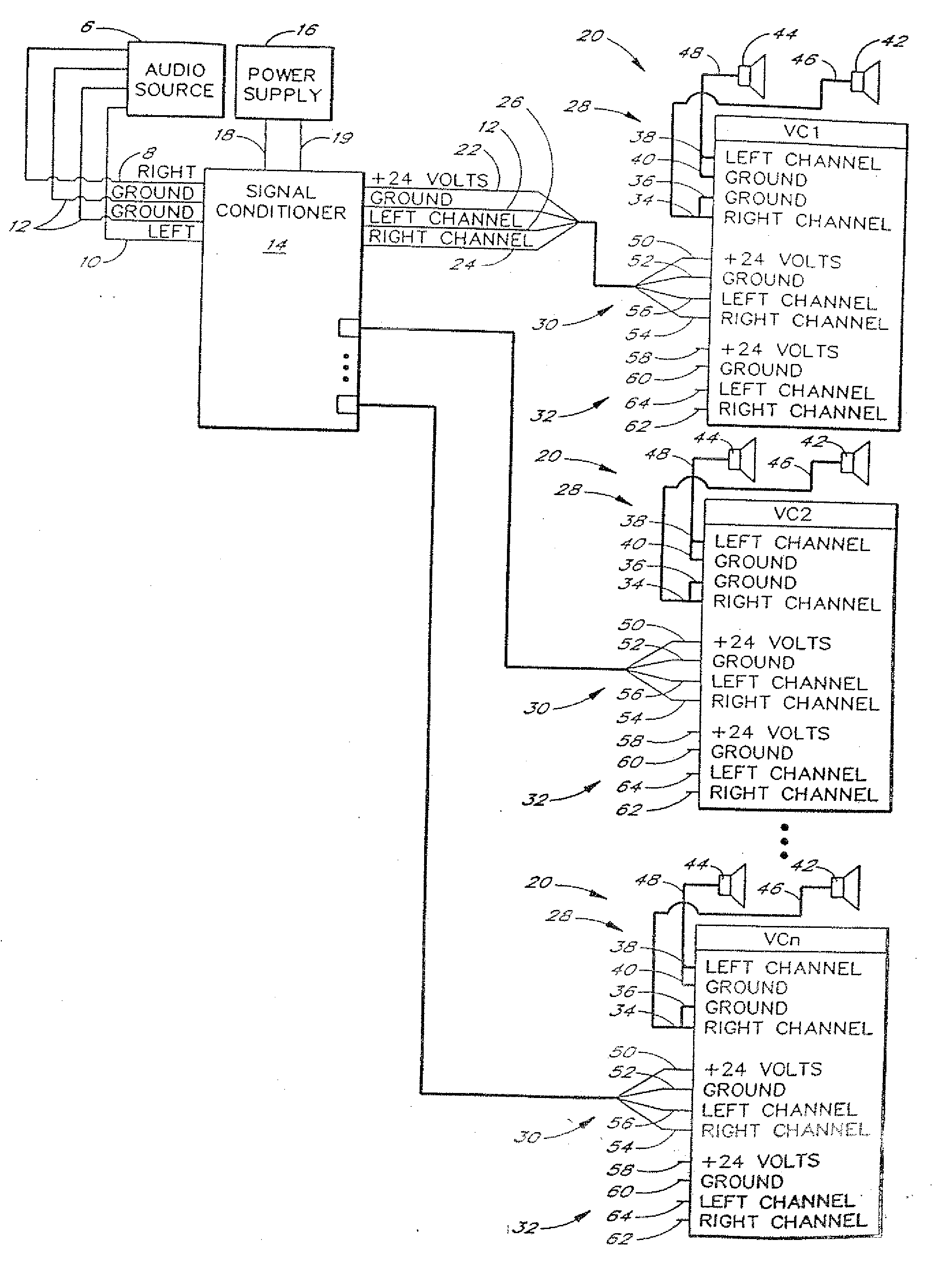
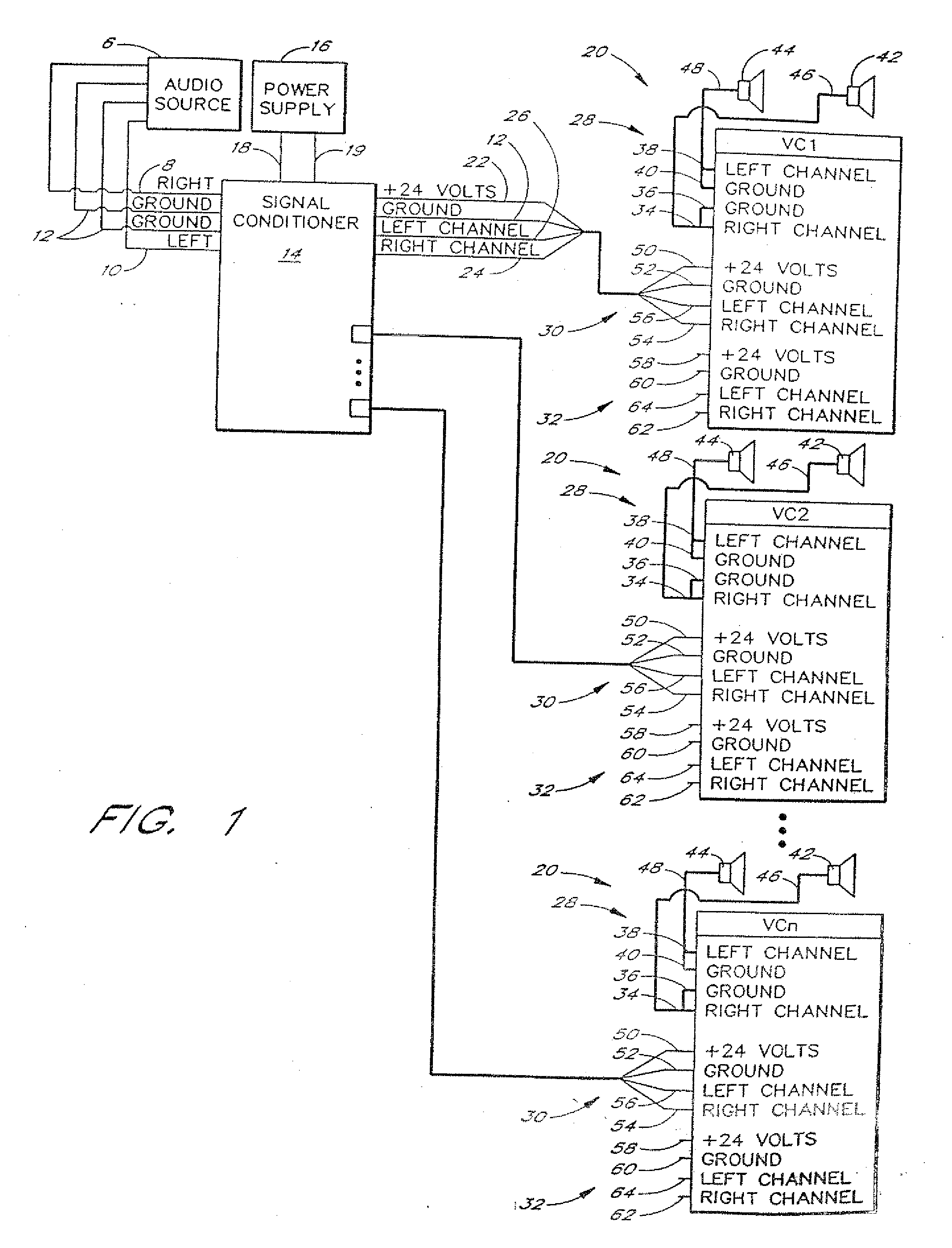
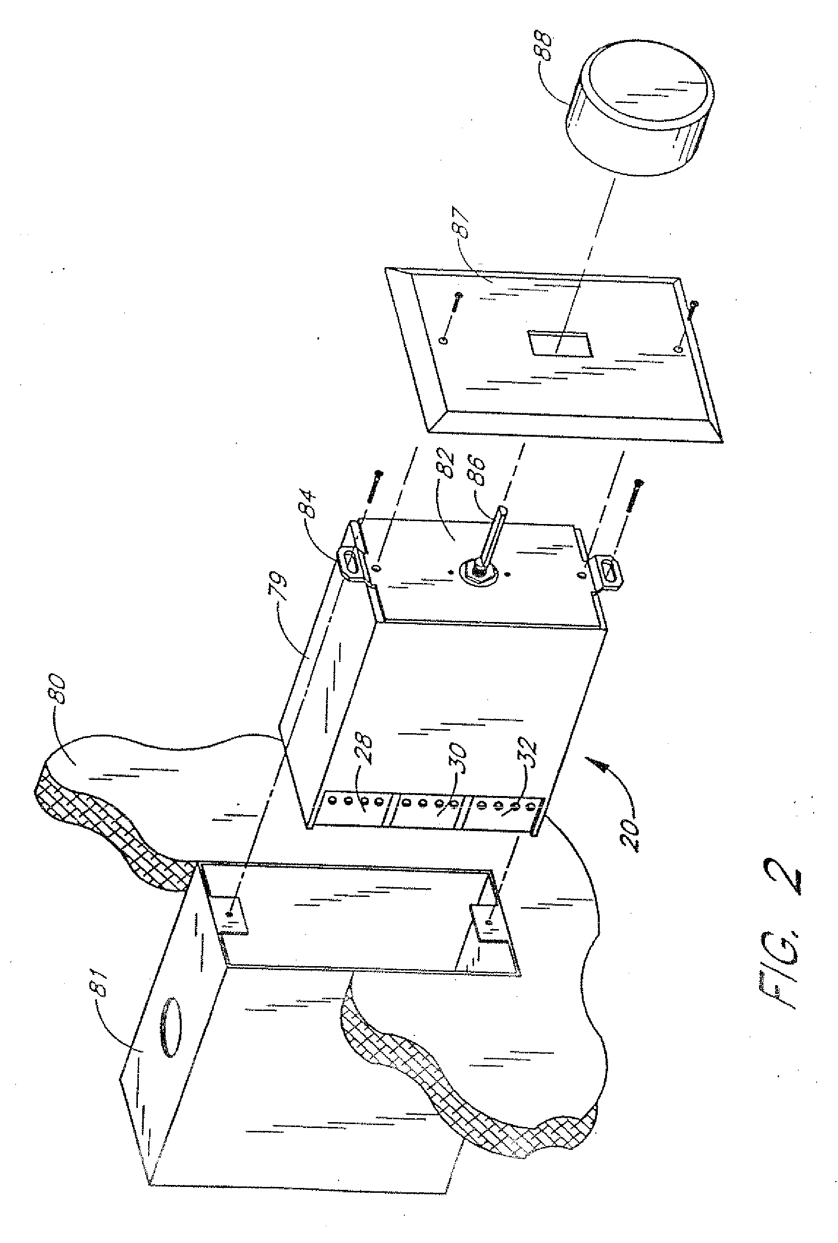
[0047]FIG. 1 illustrates the general arrangement and connection of a distributed audio system having features in accordance with one preferred embodiment of the present invention. The system generally comprises an audio source 6 having a right channel signal output line 8 and left channel signal output line 10. Both the right channel 8 and the left channel 10 are referenced to a respective ground 12. The audio source 6 provides an electrical signal representing an audio signal and may further generate a stereo signal representing a variance in the signal between the right channel 8 and the left channel 10. The audio source may comprise any number of suitable audio sources, including, without limitation, a radio tuner / receiver, tape player, phonograph, compact disc player, microphone or similar device. Alternatively, or in addition, a public addressing system (not shown) may integrate with the audio source 6 to provi...


PUM


Abstract

An audio distribution system is provided for communicating audio signals between one or more audio sources and a plurality of remote speakers. The system includes at least one audio source for generating an audio signal, and a plurality of amplified volume controls, each disposable remote from the audio source. The volume controls are operative to receive and amplify the audio signal to power associated speakers. A power supply is disposable remote from one or more of the volume controls, for generating a power supply to power all volume controls. An audio/power distribution network is connectable to the audio source, power supply and volume controls, for communicating the audio signal and power supply signal throughout the network. A plurality of audio/power distribution nodes are connected to the audio/power distribution network for interfacing the audio source, power supply and volume controls to the distribution network. The power supply and audio source may be connected to any of the distribution nodes to provide audio signal and power to each of the volume controls.

Description

RELATED APPLICATION(S)[0001]This application is a continuation of U.S. application Ser. No. 10 / 145,225, filed May 13, 2002, which is a continuation-in-part of U.S. application Ser. No. 08 / 972,868, filed on Nov. 8, 1997. The entire teachings of the above application(s) are incorporated herein by reference.BACKGROUND OF THE INVENTION[0002]The present invention relates to an audio signal amplification and distribution system for multiple speaker applications, and, in particular, to a new and improved wall-mounted “powered” volume control having an integrated audio power amplifier for connecting between a signal source and one or more remote speakers.[0003]Broadcasting audio or music, such as background music, within a facility is generally desirable to provide a relaxing or entertaining atmosphere or to enhance a desired theme or mood. In particular, buildings such as houses, hotels, restaurants, casinos, shopping malls, and other indoor or outdoor areas often are equipped with sound d...

Claims


Application Information

Patent Timeline
Patent Type & Authority Applications(United States)
IPC IPC(8): H04B3/00H04S3/00
CPCH04S3/00H04R2420/07
Inventor CURTIS, JERRYPETERSON, JAMES
Owner RUSSOUNDFMP
Why Eureka
Try Eureka