Valve
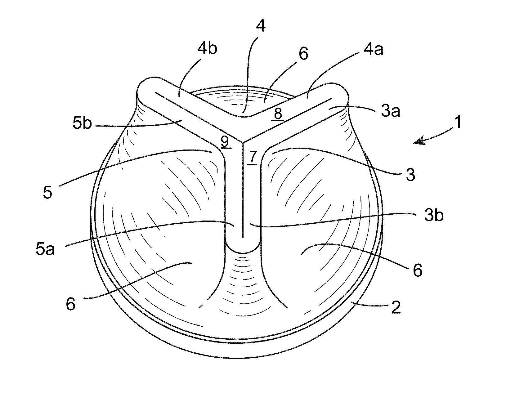
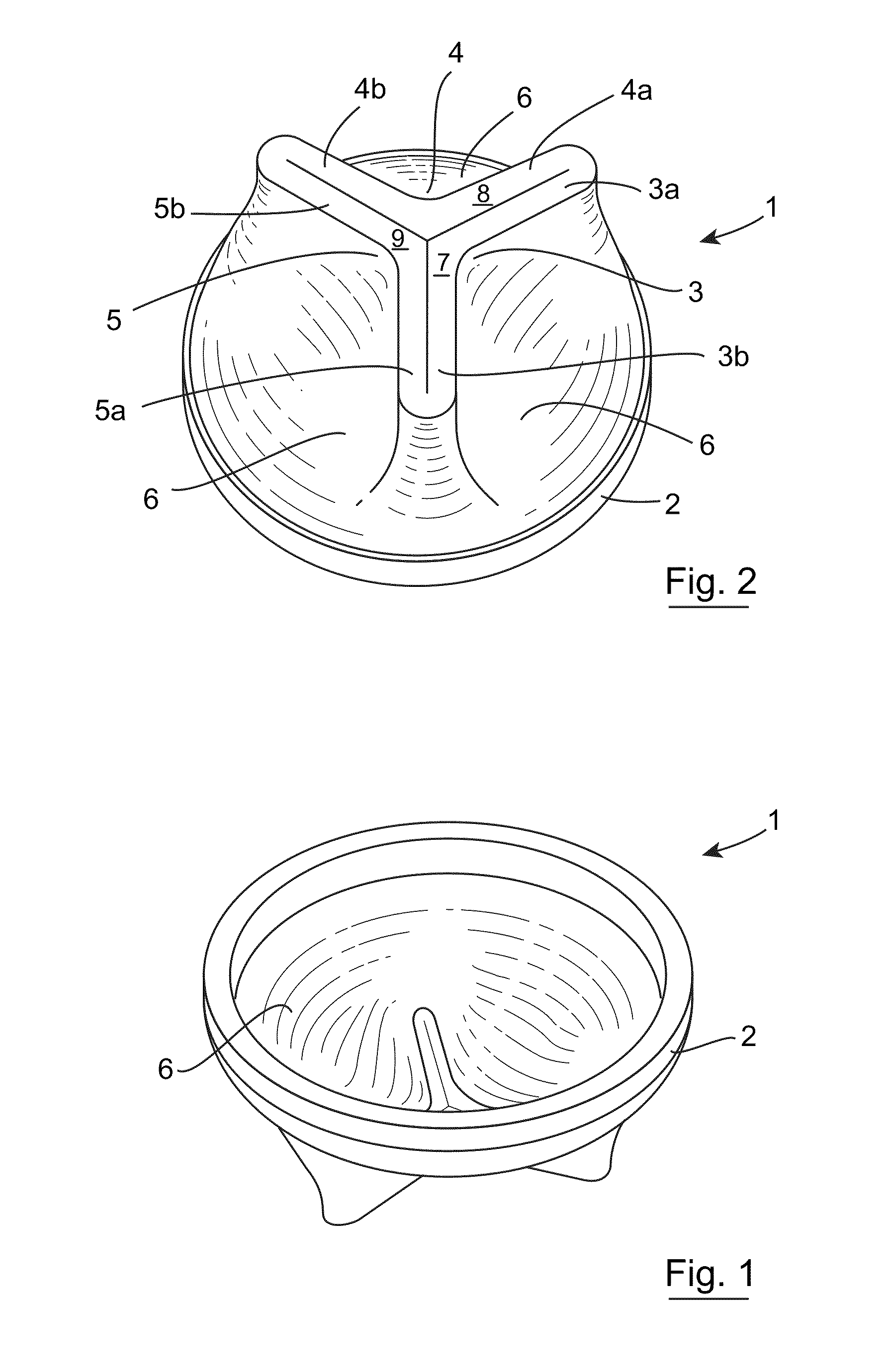
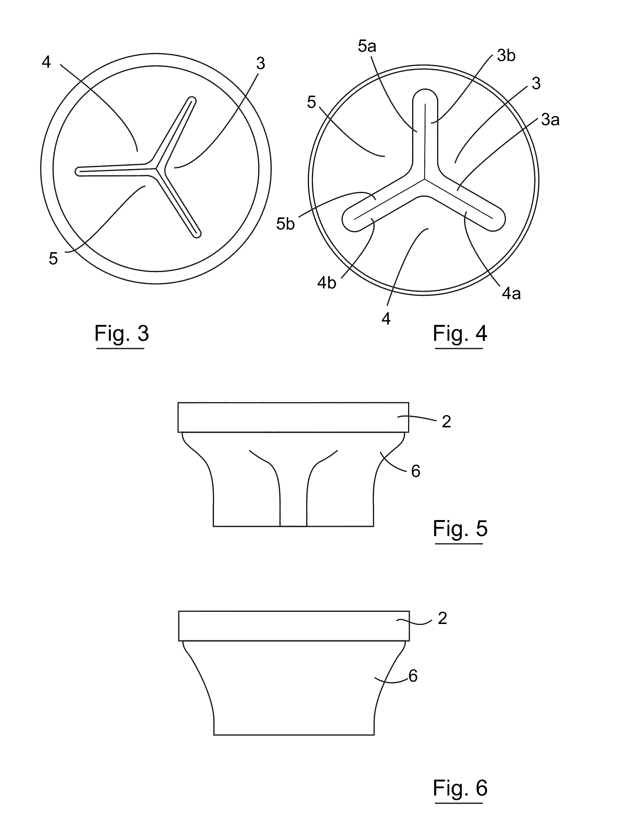
a valve and esophageal technology, applied in the field of esophageal stents, can solve the problems of significant discomfort of patients, in-stent reflux technology, and reduce the quality of life of already sick patients, and achieve the effect of reducing the diameter of at least a portion of the valve support structur
- Summary
- Abstract
- Description
- Claims
- Application Information
AI Technical Summary
Benefits of technology
Problems solved by technology
Method used
Image
Examples
example 1
Synthesis of Aliphatic Linked Fluorosiloxane Based Triblock Copolymer Pre-Soft-Segment
[0309]This is a 2 step process. In the first step silanol terminated poly(trifluoropropyl methyl siloxane) is converted into its dihydride derivative. In the next step, this dihydride derivative is reacted with the allyl terminated poly(propylene glycol).
[0310]The synthetic procedure is as follows:
[0311]Step 1:
[0312]To a 4 neck separable flask fitted with mechanical stirrer, was added 40 g of Silanol terminated poly(trifluoropropyl methylsiloxane) (FMS-9922 from Gelest Inc.) and this was mixed with 50 ml of toluene and fitted with a continuous flush of Nitrogen. To the reaction mixture 7.57 g of dimethyl chlorosilane (DMCS, from Sigma Aldrich) was added slowly over about 20 minutes keeping the temperature of the mixture constant at 30° C. With each addition of dimethyl chlorosilane, the mixture became hazy but cleared in a short period of time. Once the addition of dimethyl chlorosilane was complet...
example 2
Synthesis of Aliphatic Linked Dimethylsiloxane Based Triblock Copolymer Pre-Soft-Segment
[0315]To 130 ml of reagent grade toluene in a separable flask fitted with a mechanical stirrer, was added 64 g of allyl terminated poly(propylene glycol) (MW=700 g / mol, Jiangsu GPRO Co.) and both were mixed and heated to reflux. Then 40 g of hydride terminated poly(dimethyl siloxane) (Silmer H Di 10 by Siltech Corp.) was dissolved in 50 ml reagent grade toluene and the temperature raised to around 90° C. To this reaction mixture 2 drops of hexachloroplatinic(IV) acid (0.01M H2PtCl6 from Sigma) solution in isopropanol was added. After this catalyst solution was added, the mixture was refluxed for 1 hour and then the solvent was distilled off in order to get the final product. The reaction was followed with H-NMR and gel permeation chromatography (GPC) confirmed the final molecular weight of the product to be 2300 g / mol.
TABLE 2Polymer block ratiosStoiciometric ratios for reaction product:Polymer bl...
example 3
Synthesis of Aromatic Linked Siloxane Based Triblock Copolymer Pre-Soft-Segment
[0316]
[0317]To a 100 ml separable flask fitted with a mechanical stirrer, 15 g of hydroxy terminated polydimethyl siloxane (DMS-S14 from Gelest Inc.) was added along with 5.36 g of di-chloro p-xylene (from Sigma) and 0.0089 g of Copper(II) acetylacetonate (Cu(Acac)2 from Sigma). The reaction mixture was refluxed at 110° C. for 5 hrs. At this point, 19.77 g of hydroxy terminated poly(propylene glycol) (from Sigma) was added dropwise and the reaction mixture was then refluxed for another 15 hr. The progress of reaction was followed by 1H-NMR and the final molecular weight, determined by gel permeation chromatography (GPC), was 3000 g / mol.
[0318]H-NMR analysis: Solvent used for 1H-NMR analysis is CDCl3.
[0319]Aromatic H=7.25-7.45 ppm, —CH2=4.5-4.6 ppm, —CH3 (of PPO)=1-1.4 ppm, —CH2 (of PPO)=3.2-3.8 ppm, —OH (of PPO)=3.8-4 ppm, —CH3(silanol)=0.5-0.8 ppm.
TABLE 3Resulting polymer block ratiosStoiciometric ratios ...
PUM
| Property | Measurement | Unit |
|---|---|---|
| Fraction | aaaaa | aaaaa |
| Fraction | aaaaa | aaaaa |
| Fraction | aaaaa | aaaaa |
Abstract
Description
Claims
Application Information
 - R&D
- Intellectual Property
- Life Sciences
- Materials
- Tech Scout
- Unparalleled Data Quality
- Higher Quality Content
- 60% Fewer Hallucinations
Browse by: Latest US Patents, China's latest patents, Technical Efficacy Thesaurus, Application Domain, Technology Topic, Popular Technical Reports.
© 2025 PatSnap. All rights reserved.Legal|Privacy policy|Modern Slavery Act Transparency Statement|Sitemap|About US| Contact US: help@patsnap.com


