Bladed coal diffuser and coal line balancing device

a technology of coal diffuser and coal line, which is applied in the direction of liquid fuel burners, combustion types, lighting and heating apparatus, etc., can solve the problems of general erosion and high temperature related degradation, easy high temperature reach of impellers, and additional unfavorable consequential damages

Active Publication Date: 2010-05-20
THE BABCOCK & WILCOX CO
View PDF16 Cites 10 Cited by
  • Summary
  • Abstract
  • Description
  • Claims
  • Application Information

AI Technical Summary

Benefits of technology

[0012]In one configuration, the invention provides a ceramic diffuser located in the upstream end of the coal nozzle. The configuration of the diffuser allows the diffuser to be manufactured from ceramic and located in the cooler upstream end of the coal nozzle. The ceramic diffus

Problems solved by technology

While standard bladed impellers 12 and similarly located mixing devices can offer functional NOx improvements, they generally suffer from erosion and high temperature related degradation.
However, at these locations impellers readily reach high temperatures from radiative heat transfer from the furnace.
These high temperatures are undesirable to impeller longevity as they can thermally erode metal components directly and/or cause coal to stick and cake upon the device causing additional unfavorable consequential damages.
Pulverized coal is highly abrasive, and erosion from pulverized coal is a consistent problem for burner component in direct contact therewith.
While ceramics can minimize this effect and are frequently used to protect equipment from erosion, high temperatures near the exit of the burner coal nozzle 4 prevent the effective use of ceramics in such applications.
When combined, erosion and exposure to high temperatures generally shorten component life of impellers and similarly located devices to typically about a year of effective service life, after which the burner experiences diminished performance until such time that the impeller is replaced.
Standard impellers 12 and similarly located devices thus experience a limited effective service life in the power generation, requiring substantial expenditures (cost, material, labor, and outage time) to facilitate repeated replacements.
An additional concern of pulverized coal fired burners is the potential for non-uniform distribution of pulverized coal and primary air to multiple burners served by a given pulverizer.
Such non-uniformities are due in part to differences in co

Method used


Image

  • Bladed coal diffuser and coal line balancing device
  • Bladed coal diffuser and coal line balancing device
  • Bladed coal diffuser and coal line balancing device

Examples


Embodiment Construction

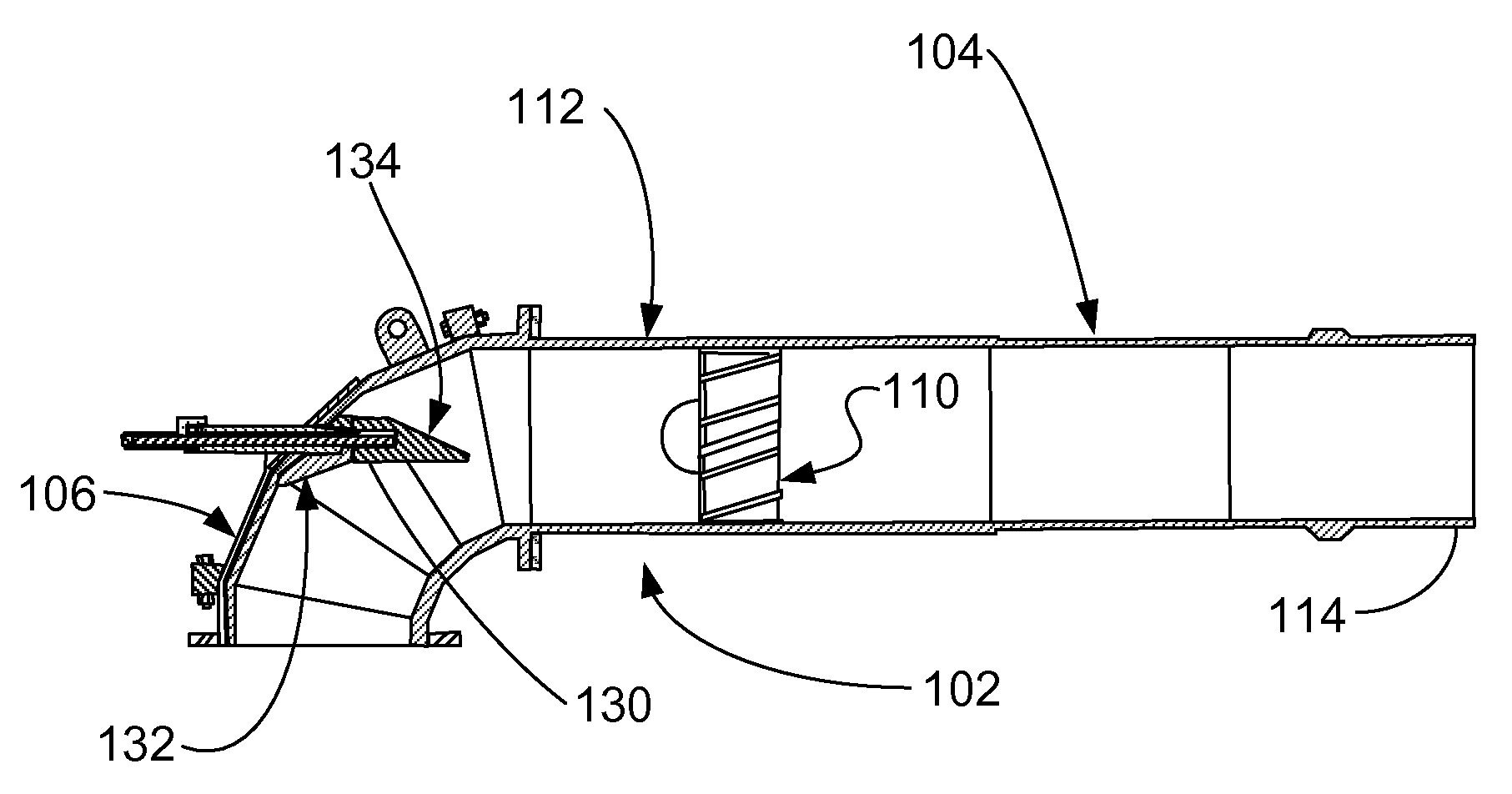
[0028]A coal nozzle assembly 102 for a pulverized coal burner includes a coal nozzle or coal nozzle pipe 104 and a burner elbow 106. Coal nozzle assembly 102 conditions the primary air / pulverized coal stream before dispensing it to the furnace. Coal nozzle assembly 102 may be used to accomplish rapid mixing of pulverized coal and secondary air in a burner to accelerate the combustion of the pulverized coal under reducing conditions in an air staged unit. The accelerated combustion oxidizes the fuel more rapidly in the burner zone to the extent air is available. The accelerated combustion provides more time for the flue gas to complete the combustion under reducing conditions before the balance of air is supplied by the over fire air system. The increased residence time under reducing conditions decreases the amount of NOx formed in the burner zone. Further, more complete combustion in the burner zone limits the amount of remaining fuel needed to burn at and above the over fire air p...


PUM


Abstract

A coal nozzle assembly for a pulverized coal burner includes a diffuser. A flow conditioner also may be used with the assembly. The assembly conditions the coal/air flow before the coal/air flow is introduced to the furnace. The flow conditioner directs the coal into the diffuser where it is swirled to form a fuel rich outer ring disposed about an air rich inner portion before the fuel is delivered to the coal nozzle.

Description

CROSS REFERENCE TO RELATED APPLICATIONS[0001]This application claims the benefit of U.S. Provisional Patent Application Ser. No. 61 / 114,501 filed Nov. 14, 2008; the disclosures of which are incorporated herein by reference.FIELD OF INVENTION[0002]The present invention concerns improvements in the field of low nitrogen oxide (NOx) pulverized coal fired burners. More particularly, the invention relates to the coal nozzle assembly that conditions the pulverized coal / primary air stream prior to combustion.BACKGROUND OF THE INVENTION[0003]Low NOx coal fired burners employ various types of hardware in the burner nozzles to alter the primary air / pulverized coal (PA / PC) stream before entering the burner throat for initiation of combustion. These devices are designed to enhance fuel / air mixing to better control NOx emissions. U.S. Pat. No. 4,380,202 discloses a conical diffuser 10 (an example of which is depicted in FIG. 1) that has been utilized in Babcock and Wilcox's DRB-XCL® and DRB-4Z® ...

Claims


Application Information

Patent Timeline
IPC IPC(8): F23D1/00B05B1/34
CPCF23D1/00F23D2201/10F23K3/02F23D2202/00F23D2900/00018F23D2201/20Y02E20/34
Inventor LARUE, ALBERT D.HAZLETT, LEONARD D.CHEN, ZUMAOTITMAS, KURT S.
Owner THE BABCOCK & WILCOX CO
Why Eureka
Try Eureka