
Therapeutic material delivery system for tissue voids and cannulated implants

a technology of tissue voids and therapeutic materials, applied in the field of drug delivery, can solve the problems of difficult to achieve, difficult to confirm placement, and difficulty in detecting the depth of needle penetration in the bone itself,

Active Publication Date: 2010-05-20
BIOACTIVE SURGICAL
View PDF16 Cites 42 Cited by
  • Summary
  • Abstract
  • Description
  • Claims
  • Application Information

AI Technical Summary

Benefits of technology

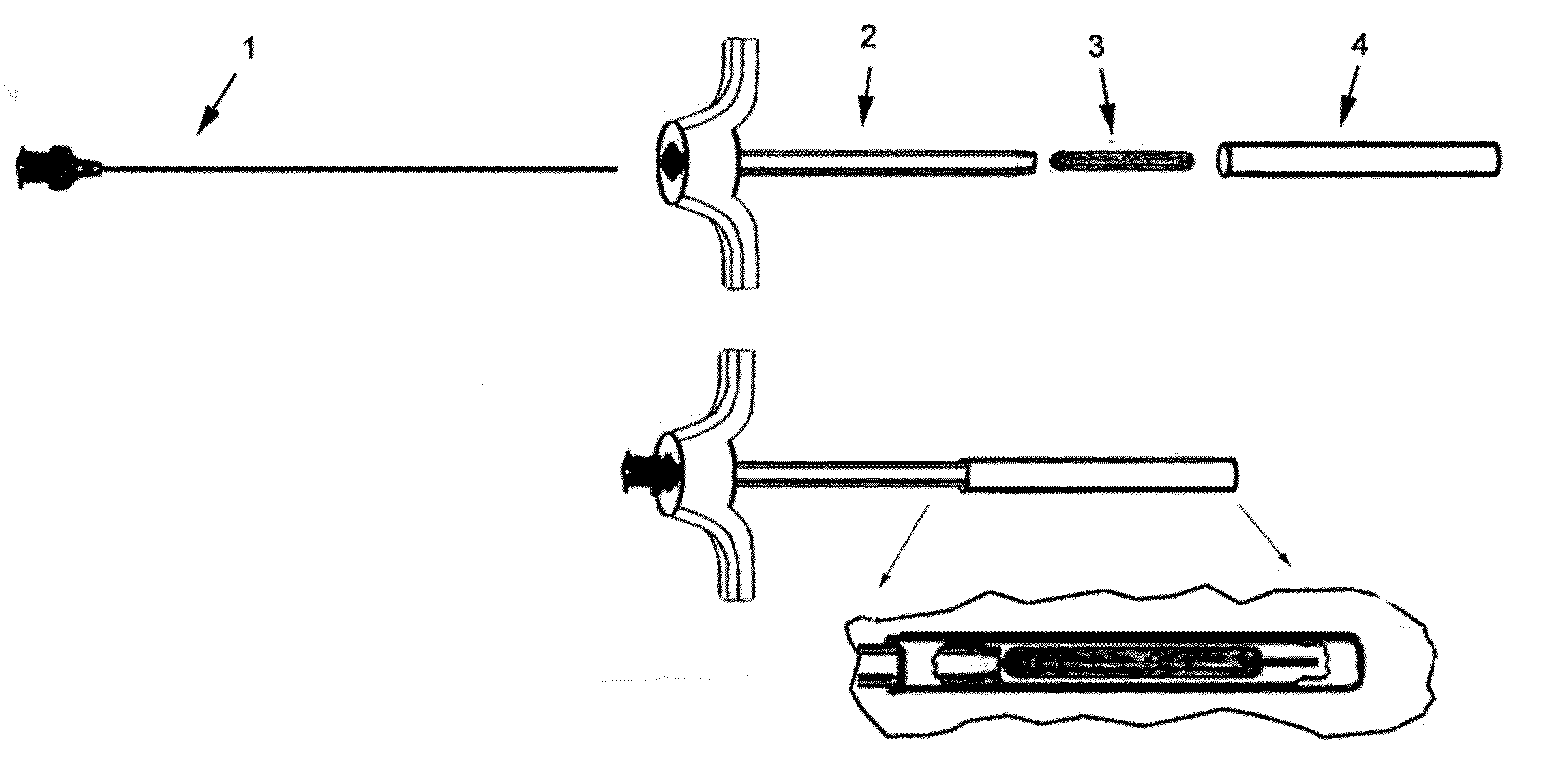
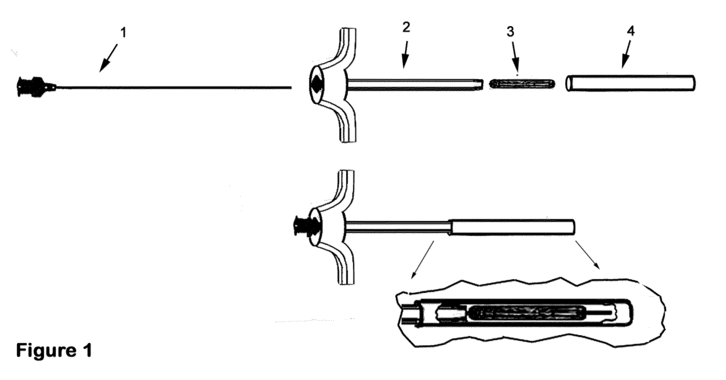
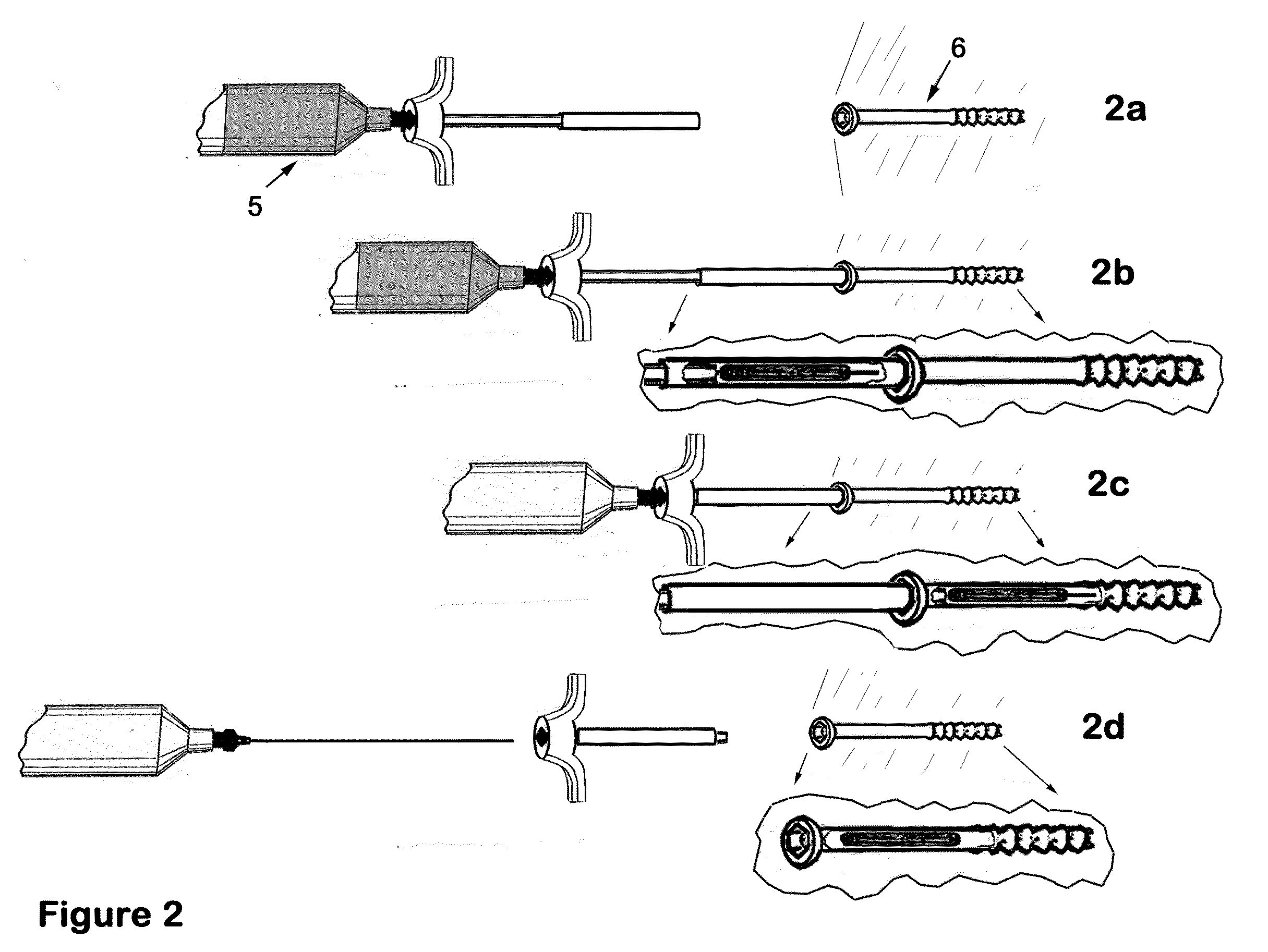
[0016]To achieve the desired effects, the present invention also contemplates the use of a core device comprising an injection port, such as a hypodermic needle or similar fluid delivery cannula, wherein a portion of the length of the needle is surrounded by, or adjacent to, the plug, further wherein the length of needle and plug are contained and constrained in a radial direction in a delivery tube or “plug guide”, for example a cannula. Positioned on the proximal side of the plug within said plug guide is a plunger device, or “plug pusher”, wherein the hypodermic needle passes along the linear axis of the plug pusher such that therapeutic material can be delivered by a syringe or other reservoir system from the proximal side of the plug pusher, through and to the distal side of the plug. Further, the radial orientation of the plug with respect to the hypodermic needle may be established prior the surgical procedure, for example as a pre-packaged assembly. In this manner, one may avoid the awkward and cumbersome task of coordinating the plug, plunger, and needle in the midst of the procedure, i.e., during or subsequent to the insertion of the plug into the tissue of the implant device, and thereby obviate the need for the needle to have to establish a channel through the plug after it has been inserted The plug is of a nature where, once in the target location (e.g., a bone cavity or hole), it can expand or otherwise deform (or expand) to create a flow restriction within the cavity; alternately, the plug can deform the cavity to achieve the same end (i.e., a full or partial hydraulic barrier that impedes fluid flow). The hypodermic needle can then be used to inject therapeutic material into the now isolated area of the void in tissue on the distal side of the plug. In one embodiment, the plug is fabricated from a self-sealing material capable of expanding or otherwise deforming to seal the needle path. Alternatively, the surrounding tissue can itself contract or deform to form the requisite fluid seal. In either case, the hypodermic needle can then be removed while the plug remains in place, acting in conjunction with the surrounding tissue to seal the needle path. It is further an aspect of the present invention that the plug pusher can be maintained in a position which secures the plug in place in the tissue or implant device while the needle is being removed, thereby eliminating the potential for the plug position to be altered appreciably by interaction with the needle as it is being removed.
[0022]In a preferred embodiment, the plug guide cannula of the present invention is dimensioned such that the inside diameter of its distal end is approximately equal to or less than the inside diameter of the bore of the bone screw, other implant device or hole in the tissue. In this manner, the plug retained therein can be pushed from the plug guide and into the bore with minimal of disruption of the plug. Additionally, the distal end of the plug pusher, which abuts the proximal side of the plug, may be displaced through the plug guide cannula to a point approximately flush with the plane of the juncture of the plug guide cannula and the opening into the tissue void or bore of the implant device. Alternatively, the distal end of the plug pusher may extend a predetermined distance into the tissue or implant device to ensure secure deployment of the plug.

Problems solved by technology

Problematic issues associated with the accurate and efficient placement of such therapeutic, remedial or other beneficial material at a specific points in a surgical penetration, such as one bridging the juncture of two bone sections, include, for example:1. In those cases where the therapeutic material is injected through a hypodermic needle, difficulty can arise from the fact that confirmation of the needle tip location relative the juncture point is not easily available.
In the case of minimally invasive techniques, the depth of soft tissue over the bone varies between patients and body areas and can actually fluctuate during surgery because of soft tissue swelling.
Consequently, the depth of needle penetration in the bone itself may not be readily apparent, and use of radiological or other imaging means to confirm placement requires expensive equipment and is time consuming.
Further, needle penetration into a bone screw or other device which is opaque to imaging technologies must be inferred rather that directly observed, which introduces an element of potential error.2. Injected therapeutic material tends to rapidly flow out of the desired zone of application, particularly in the proximal direction (away from the target site), most often though the very hole created in the bone for the surgical procedure.3. The therapeutic material may need to be introduced under pressure to successfully penetrate the surrounding tissue of interest, and an open hole does not support this pressurization.
However, since cannulated screws are open at both ends, there is the potential for the expensive therapeutic material being introduced to flow out either end of the screw, rather than through the fenestrations, as desired.
To address the issue of leakage, specially designed screws with integral valves have been proposed to prevent flow out of the proximal end or “head” of a bone screw; however, these type devices have the disadvantages of being overly specialized for a particular application.
In addition, they are in many cases not compatible with the standard hex head driver tools available in many operating rooms.
However, these also interfere with the driving of the screw or need to be installed after the screw is in place, potentially requiring unobstructed access to the screw head, which is not always possible.
The guidewire makes the pre-placement of a flow restriction in a screw prior to screw placement problematic.

Method used


Image

  • Therapeutic material delivery system for tissue voids and cannulated implants
  • Therapeutic material delivery system for tissue voids and cannulated implants
  • Therapeutic material delivery system for tissue voids and cannulated implants

Examples


example 1

Treatment of Chronic Degenerative Insertional Tendiopathy

[0141]Surgical treatment is provided for a patient with chronic degenerative insertional tendinopathy with thickening fibrosis and tearing of the Achilles tendon from the calcaneus extending approximately 5-6 cm, who has failed conservative treatment. In surgery, the peritinon is incised, the tendon is debrided and all non-viable tendon is removed, the diseased portion of the calcaneus is resected, and the flexor hallucis longus (FHL) tendon is approached. A section of the FHL tendon is harvested and formed into a 5 mmØ×3 mm plug and inserted and securely packed into a plug guide cannula of the present invention by trained personnel. A 2 mmØ guide wire is driven into the calcaneus at the desired point of reattachment of the tendon. A 5 mmØ cannulated drill is then used over the guide wire to create the attachment tunnel. The free end of the portion of FHL tendon which remains attached to muscle is sutured and passed through th...

example 2

Treatment of Osteopenia and Interochanteric Femur Fracture

[0142]Surgical treatment is provided for a patient with an osteopenia and intertrochanteric femur fracture. The fracture is reduced and a hip screw and plate device is surgically inserted and affixed using 4.5 mmØ×4 cm cannulated titanium screws. In the process of screw placement, the screws are driven to a point representing 75% of the final insertion depth. At that point, a device of the present invention is utilized in conjunction with the screw. The device comprises, in part, a calcium putty plug, and has attached to the needle, a reservoir of methyl-methacrylate bone cement. The device is abutted to the partially inserted screw; the plug pusher is displaced into the plug guide cannula to a point where the plug and the needle tip are displaced into the target screw. The bone cement is then injected into the screw. The needle is removed, and then the plug pusher is removed. The screw is then driven the remaining portion to...

example 3

Avascular Necrosis of the Femoral Head

[0143]A patient with avascular necrosis of the femoral head prior to the onset of subchondral fracture undergoes a procedure for structural decompression that involves core drilling, flushing of the affected zone with a solution thought to halt osteoclastic breakdown (in cases of suspected infection, an antibiotic treatment may be added or substituted), and then treatment of the area with cellular therapy through the insertion of mesenchymal stem cells (MSC) in a autologous plasma matrix which also contains therapeutic levels of platelet-derived growth factor (PDGF). This is accomplished through the following procedure:[0144](a) An incision is made to access the trochanteric section of femur.[0145](b) A 6.5 mmØ outside×60 mm surgical cannula is introduced into the incision and placed on the bone as a guide.[0146](c) A 5 mm drill is introduced into the cannula and under image guidance the affected area is penetrated by a plurality of holes origin...


PUM


Abstract

Described herein is a novel drug delivery assembly having particular applicability to the field of orthopedic and surgical medicine. The devices and assemblies described herein enable the efficient application and retention of potentially expensive therapeutic materials to very specific locations, particularly those associated with voids in bone and tissue. One particularly unique aspect of the present invention involves the introduction of constructs which promote the retention of therapeutic material in the target area of application for beneficial use, for example by forming a proximal barrier that prevents leakage of the therapeutic material out of the target area. Additionally, the present invention provides unique devices and methods for surgical introduction of such constructs. The present invention finds particular application in connection with introduction of stem and progenitor cells, bioactive molecules and bone scaffold materials in conjunction with bone voids and with the use of cannulated implants, such as bone screws (also surgical screws) and pins. The present invention also has beneficial use in the delivery of cancer drugs, antimicrobials, bone cements and other therapeutic materials.

Description

PRIORITY[0001]The instant disclosure extends concepts enumerated in and claims priority to U.S. Provisional Application Ser. Nos. 61 / 116,465, filed Nov. 20, 2008 (Attorney Docket No.: BST-002P), and 61 / 154,718, filed Feb. 23, 2009 (Attorney Docket No.: BST-002P2), the entire contents of which hereby are incorporated by reference herein.FIELD OF THE INVENTION[0002]The present invention relates to drug delivery, particularly in the field of orthopedic and surgical medicine. More particularly, the invention relates to devices and assemblies that enable the efficient application and retention of potentially expensive therapeutic materials to very specific locations, particularly those associated with voids in bone and tissue.[0003]One particularly unique aspect of the present invention involves the introduction of constructs which promote the retention of therapeutic material in the target area of application for beneficial use, for example by forming a proximal barrier that prevents le...

Claims


Application Information

Patent Timeline
IPC IPC(8): A61M5/178A61F2/28A61M1/00
CPCA61B17/0057A61B17/3468A61M31/00A61B17/3478A61B17/864A61B17/3472
Inventor SPEDDEN, RICHARD H.SCHON, LEW C.PINGEL, LAURA J.
Owner BIOACTIVE SURGICAL
Learn More