Display device

a display device and display technology, applied in the direction of electric variable regulation, process and machine control, instruments, etc., can solve the problems of large power consumption, difficult to see the image displayed thereon in a dark place, small power consumption, etc., and achieve the effect of preventing detection errors

Active Publication Date: 2010-05-27
JAPAN DISPLAY WEST
View PDF6 Cites 17 Cited by
  • Summary
  • Abstract
  • Description
  • Claims
  • Application Information

AI Technical Summary

Benefits of technology

[0028]Since the voltage of the capacitor decreases exponentially, it takes a long time until the voltage of the capacitor becomes a value not more than the threshold value when the illumination of the external light is too low, which causes such a problem that the measurement value may not be obtained within a predetermined measurement period. In addition, the brightness range which is the most comfo

Problems solved by technology

The liquid crystal display device of the reflection type is advantageous in that the power consumption is small since the external light is used as a light source, but is disadvantageous in that an image displayed thereon is difficult to be seen in a dark place.
The liquid crystal display device of the transmission type is advantageous in that an image displayed thereon is easily seen even in a dark place, but is disadvantageous in that the power consumption is large since the backlight unit is required to be turned on all the time.
However, when the photo diode is used as the optical sensor, a problem arises in that the number of manufacture processes of the liquid display panel increases.
For this reason, according to the known illumination measuring method, since the delay time period t10 in the bright state becomes longer than the delay time period t12 in the dark state, a problem arises in that the brightness control of the backlight unit is late particularly when the peripheral environment becomes bright suddenly.
However, it is disadvantageous in that a manufacture cost increases when a pl

Method used


Image

  • Display device
  • Display device
  • Display device

Examples


first embodiment

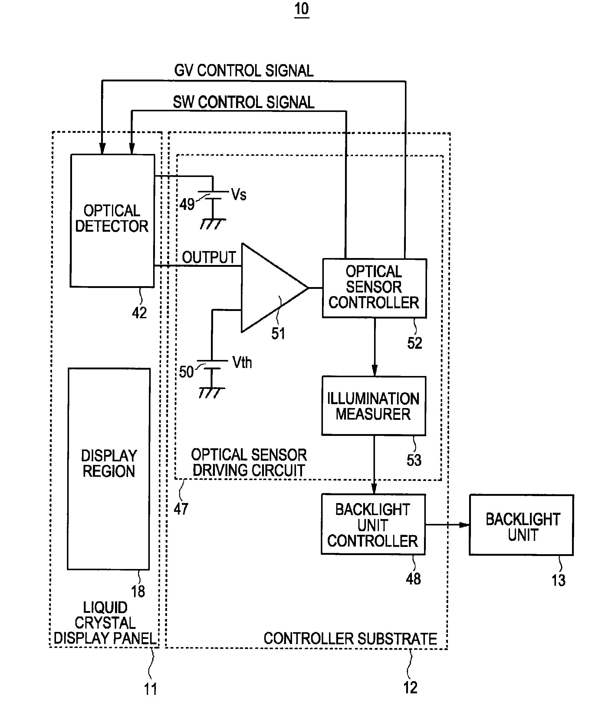
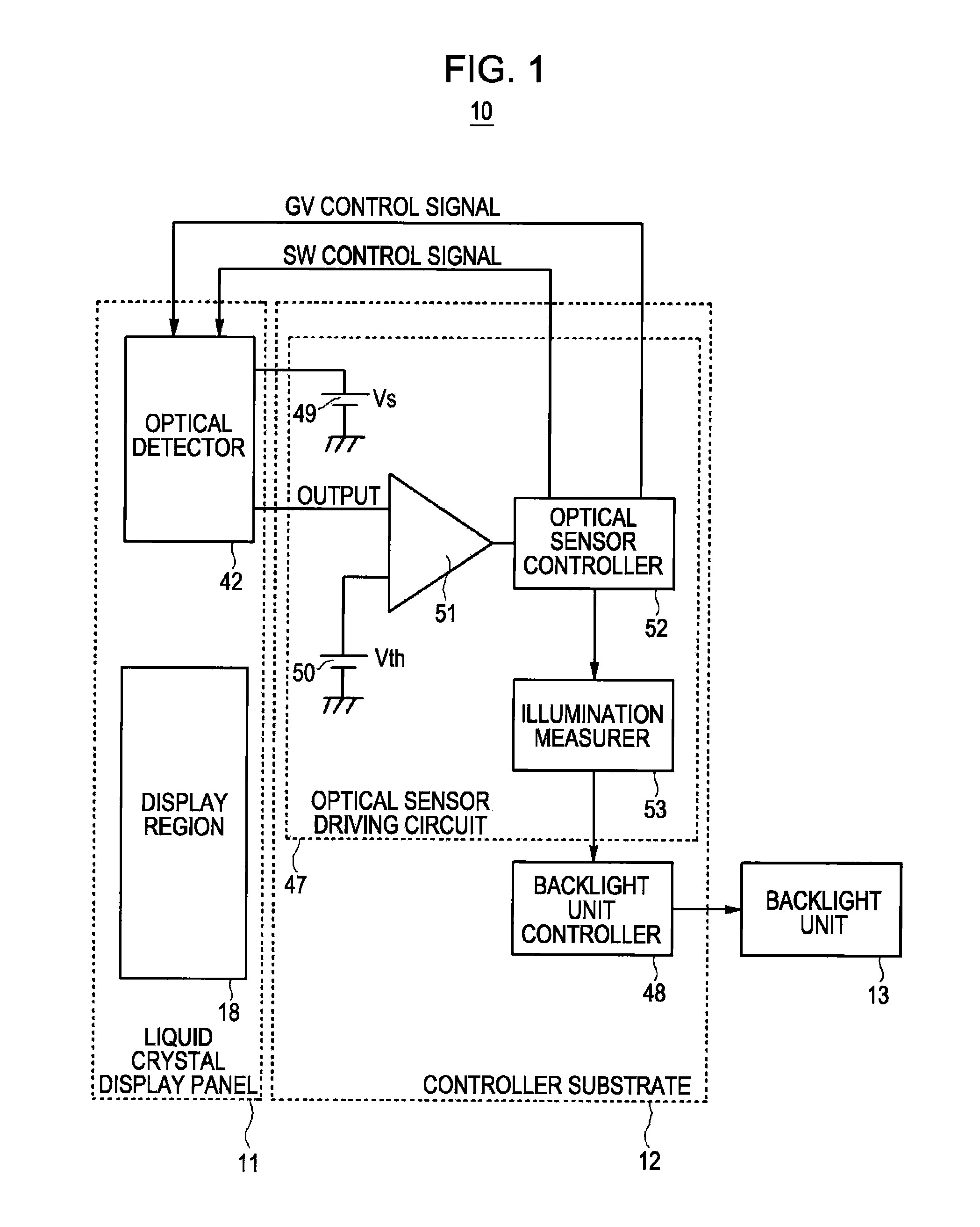
[0060]Next, an operation of the optical sensor driving circuit 47 of the liquid crystal display device 10 according to the first embodiment will be described with reference to FIGS. 1, 7, and 8. When the optical sensor driving circuit 47 starts to be operated in a power-on state, the optical sensor controller 52 outputs the GV control signal so that a voltage GV of the gate electrode GL of the optical sensor TFTL formed by the TFT is in an off state (inverse bias state) (step S11). Accordingly, a current flowing between the source electrode SL and the drain electrode DL of the optical sensor TFTL formed by the TFT is only a leakage current generated by the light. Then, the optical sensor controller 52 initializes an internal counter (not shown) (step S12). The counter has a function of measuring time by counting the number of pulses in accordance with a clock pulse signal of a predetermined frequency. Then, the optical sensor controller 52 turns on the switch SW (step S13), and outp...

second embodiment

[0069]Next, an operation of the optical sensor controller 52 of the liquid crystal display device 10 according to the second embodiment will be described with reference to FIGS. 1, 9, and 11. In addition, in the optical sensor controller 52 according to the second embodiment, the same reference numerals will be given to the same components as those of the optical sensor controller 52 according to the first embodiment, and the detailed description thereof will be omitted.

[0070]Step S11 to step S21 in the flowchart of the optical sensor controller 52 according to the second embodiment shown in FIG. 9 are the same as step S11 to step S21 in the flowchart of the optical sensor controller 52 according to the first embodiment shown in FIG. 7. When step S19, step S20, and step S21 end, the optical sensor controller 52 according to the second embodiment carries out step S22, the period during which the gate electrode GL of the optical sensor TFTL formed by the TFT is turned on is calculated...


PUM


Abstract

A display device includes: a display panel; an optical detector which includes an optical sensor formed by a thin film transistor for detecting external light and a capacitor connected between a pair of electrodes of the optical sensor; a switch which turns on or off a charging operation of the capacitor; an optical sensor controller which controls the switch to be turned on or off and measures illumination of the external light on the basis of a time period during which the switch is turned off and a voltage of the capacitor becomes a value not more than a threshold value; and a controller which controls brightness of the display panel on the basis of an output of the optical sensor controller, wherein after the optical sensor controller detects a fact that the voltage of the capacitor becomes the value not more than the threshold value, the optical sensor controller turns on the switch after a predetermined time.

Description

BACKGROUND[0001]1. Technical Field[0002]The present invention relates to a display device equipped with an optical sensor which is formed by a TFT (Thin Film Transistor) for detecting external light and an optical detector which has a capacitor connected between a pair of electrodes of the optical sensor. More specifically, the present invention relates to a display device equipped with an optical sensor and an optical detector capable of allowing a display screen to be quickly seen by quickly detecting external light particularly when a peripheral environment changes from a dark state to a bright state.[0003]2. Related Art[0004]As display devices, there are known various display devices such as a CRT (Cathode Ray Tube), a liquid crystal display device, an LED (Light Emitting Diode) display device, a plasma display device, and an organic EL display device. Among the various display devices, the liquid crystal display device is more widely used than the CRT for the purpose of a displ...

Claims


Application Information

Patent Timeline
IPC IPC(8): H05B37/02
CPCG09G3/3406H05B33/0854G09G2360/144H05B45/12
Inventor KUNIMORI, TAKASHIHIRABAYASHI, YUKIYA
Owner JAPAN DISPLAY WEST
Why Eureka
Try Eureka