Hydraulic fluid and hydraulic system

a hydraulic system and hydraulic fluid technology, applied in the direction of lubricant composition, organic chemistry, fuels, etc., can solve the problems of unrecoverable elastic energy, volume change rate, and unignorable amount of energy loss, and achieve excellent responsiveness, high bulk modulus, lubricity and thermal stability

Active Publication Date: 2010-05-27
IDEMITSU KOSAN CO LTD
View PDF11 Cites 14 Cited by
  • Summary
  • Abstract
  • Description
  • Claims
  • Application Information

AI Technical Summary

Benefits of technology

[0140]According to this exemplary embodiment, since an ester that has two or more ring structures, the two or more ring structures being at least one selected from an aromatic ring and a saturated naphthenic ring, is used as a base oil, a hydraulic fluid having high bulk modulus, lubricity and thermal stability can be obtained.
[0141]Particularly, when a carboxylic acid ester having two or more aromatic rings is used as a base oil, low energy loss due to compression, excellent responsiveness when being used, for instance, in a hydraulic circuit, and energy-saving, high-speed operation and high precision of control in the hydraulic circuit are obtained. Moreover, high density of the carboxylic acid ester results in a small difference between a concentration of dissolved gas under high pressure and a concentration of dissolved gas under ambient pressure, so that less air bubbles are generated, for example, in a reservoir tank. Even if air bubbles are generated, a difference in relative density between the carboxylic acid ester and the air bubbles is large, thereby facilitating air bubble separation. Accordingly, decrease in control of hydraulic pressure, occurrence of cavitation and erosion caused by generation of air bubbles can be prevented. As noted above, the compounds of this exemplary embodiment are highly effective also in a low-pressure hydraulic circuit and are excellent in applicability.
[0142]The carboxylic acid ester to be preferably used is at least any one selected from a compound including the aromatic ester skeleton structure represented by the general formula (1) below; a compound including the phenyl benzoate skeleton structure represented by the general formula (2) below; the aromatic carboxylic acid diester compound of diol represented by the general formula (3) below; and the aromatic alcohol diester compound of the dibasic acid represented by the general formula (4) below. Accordingly, a specific working effect of high bulk modulus is provided.
[0143]A specific working effect of providing a compound of an appropriate viscosity is obtained particularly when X and Y in the general formulae (1) and (2) are any one selected from an alkyl group that may include a cycloalkyl group or an aromatic group having carbon atoms of 1 to 30, a cycloalkyl group or an aromatic group having carbon atoms of 5 to 12, an alkyloxycarbonyl group that may include a cycloalkyl group or an aromatic group having carbon atoms of 2 to 30, or an alkylcarbonyloxy group that may include a cycloalkyl group or an aromatic group having carbon atoms of 2 to 30; R1 and R2 in the general formulae (3) and (4) are hydrogen or an alkyl group having carbon atoms of 1 to 10; A in the general formula (3) is an alkylene group having carbon atoms of 2 to 18 that may contain oxygen in a main chain and include a side chain; and Z in the general formula (4) is an alkylene group having carbon atoms of 1 to 18 that may include a side chain.
[0144]When a carboxylic acid ester of 10 mass % or more, preferably 30 mass % or more, more preferably 40 mass % or more is included as the base oil, a specific working effect to increase bulk modulus is obtained.
[0145]Accordingly, the hydraulic fluid of this exemplary embodiment is preferably usable in a hydraulic circuit, which is a hydraulic system in a hydraulic equipment, as a relatively high-pressure hydraulic system such as a construction machine, an injection molding machine, a press machine, a crane, a machining center, a hydrostatic continuously variable transmission, a robot and a machine tool. Moreover, the hydraulic fluid of this exemplary embodiment is preferably applicable in a hydraulic circuit of a low-pressure hydraulics, further in a servo hydraulic control circuit, a damper, a brake system and a power steering.

Problems solved by technology

When a working pressure applied on a hydraulic fluid to be used becomes 20 MPa or more in a hydraulic equipment, unignorable amount of energy loss is caused on account of decrease in volume of the hydraulic fluid by compression.
For instance, when a mineral oil having bulk modulus K of 1.4 GPa is used at 28 MPa, according to the above formulae (1) and (II), a volume change rate is decreased by 2% and hydraulic energy is maintained as 1% elastic energy in the mineral oil, but the elastic energy is not recovered and ends up in energy loss.
Especially, in an axial piston pump in which a concave piston is provided for decreasing a moving mass, such an arrangement that dead volume is set to be the same as displacement volume even in full stoke has been widely used, which causes 2% energy loss.

Method used


Image

  • Hydraulic fluid and hydraulic system
  • Hydraulic fluid and hydraulic system
  • Hydraulic fluid and hydraulic system

Examples


first exemplary embodiment

[0093]A first exemplary embodiment of the invention will be described in detail below.

[Arrangement of Base Oils]

[0094]A hydraulic fluid in the first exemplary embodiment includes a specific ester as a base oil and an additive as necessary.

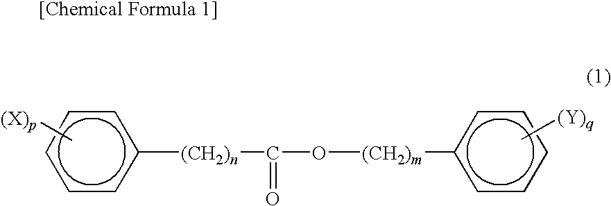
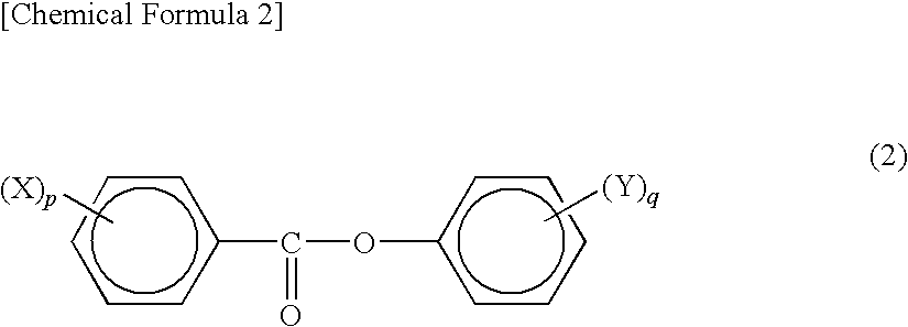
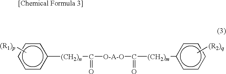
[0095]The specific ester is an ester that has two or more ring structures, the two or more ring structures being at least one selected from an aromatic ring and a saturated naphthenic ring. A preferable arrangement of such an ester is exemplified by dibasic acid diester, diester of diol or diester or triester of triol. Particularly, it is preferable that at least one of the ring structures is an aromatic ring in such an ester.

[0096]A manufacturing method of synthesizing the above ester of the first exemplary embodiment will be described in detail below. The ester is easily obtainable by reacting carboxylic acids, carboxylic acid esters, carboxylic acid chlorides or derivatives thereof with alcohol or derivatives thereof.

[0097]The aromatic ring or n...

second exemplary embodiment

[0148]Next, a second exemplary embodiment of the invention will be described in detail below.

[0149]It should be noted that a duplicated description of the first exemplary embodiment is omitted in this exemplary embodiment.

[Arrangement of Base Oils]

[0150]A hydraulic fluid of this exemplary embodiment includes a synthetic lubricating oil containing a nitrobenzoic acid ester having one nitro group as a base oil, or a mixture of the nitrobenzoic acid ester and a base oil other than nitrobenzoic acid esters as needed.

[0151]Examples of raw materials of the nitro benzoic acid ester include a carboxylic acid, a carboxylic acid ester, a carboxylic acid chloride or derivatives thereof and alcohol or derivatives thereof.

[0152]An aromatic ring of the nitrobenzoic acid ester may be substituted or unsubstituted with an alkyl group and the like. The alkyl group may be provided by alkylation after esterification, alternatively, by alkylation before esterification.

[0153]When the nitrobenzoic acid es...

example 1

[0176]Next, the first and second exemplary embodiments will be described further in detail with Examples and Comparatives.

[0177]It should be noted that the invention is not limited to the description of the following Examples and the like.


PUM

PropertyMeasurementUnit
tangential bulk modulusaaaaaaaaaa
viscosity indexaaaaaaaaaa

Abstract

A hydraulic fluid of the present invention contains, as a base oil, an ester having two or more ring structures, the two or more ring structures being at least one selected from an aromatic ring and a saturated naphthenic ring. Particularly, the hydraulic fluid contains an ester having two or more aromatic rings as the base oil. The hydraulic fluid has low energy loss due to compression and exhibits excellent responsiveness when being used in a hydraulic circuit. Consequently, the hydraulic fluid realizes energy-saving, high-speed operation and high precision of control in the hydraulic circuit.

Description

TECHNICAL FIELD[0001]The present invention relates to a hydraulic fluid having a high bulk modulus and a hydraulic system using the hydraulic fluid.BACKGROUND ART[0002]A variety of hydraulic equipments using a hydraulic fluids such as a construction machine, an injection molding machine, a press machine, a crane and a machining center have been widely used. A variety of oils have been used in these hydraulic equipments (see, for instance, Patent Document 1 or 2).[0003]Patent Document 1 discloses a hydraulic fluid for a vibration suppression damper that has bulk modulus of 1.3 or more, a viscosity index of 110 or more and a pour point of minus 25 degrees C. or less, and is specifically arranged to include poly α-olefin, polyol ester and polyether.[0004]Patent Document 2 discloses a lubricating oil, e.g. a compressor oil, a turbine oil and a hydraulic fluid, that is used for a lubricating system requiring a large working load, and is arranged to include alkyl diphenyl and alkyl diphen...

Claims


Application Information

Patent Timeline
Patent Type & Authority Applications(United States)
IPC IPC(8): C10L1/19C07C69/76
CPCC10M2207/2855C10M2207/2845C10M2215/202C10N2220/022C10N2220/023C10N2220/032C10N2220/10C10N2230/02C10N2230/64C10N2240/08C10M105/34C10M105/36C10M105/38C10M105/56C10M171/02C10M2207/2805C10M2207/2815C10M2207/2825C10M2207/2835C10M2215/003C10N2020/02C10N2030/02C10N2040/08C10N2020/011C10N2020/017C10N2020/081C10N2030/64C10M105/32C10N2020/00
Inventor TSUBOUCHI, TOSHIYUKI
Owner IDEMITSU KOSAN CO LTD
Why Eureka
Try Eureka