Red phoshorescent compound and organic electroluminescent device using the same

a technology of organic electroluminescent devices and phosphorescent compounds, which is applied in the direction of thermoelectric devices, platinum group organic compounds, other domestic articles, etc., can solve the problem of difficulty in achieving high luminance efficiency of oeld

Active Publication Date: 2010-06-03
LG DISPLAY CO LTD
View PDF3 Cites 14 Cited by
  • Summary
  • Abstract
  • Description
  • Claims
  • Application Information

AI Technical Summary

Benefits of technology

[0003]The present disclosure relates to a red phosphorescent compound and an organic electroluminescent device (OELD) and more particularly to a red phosphorescent compound having high color purity and high luminescent efficiency and an OELD using the red phosphorescent compound.
[0003]The present disclosure relates to a red phosphorescent compound and an organic electroluminescent device (OELD) and more particularly to a red phosphorescent compound having high color purity and high luminescent efficiency and an OELD using the red phosphorescent compound.
[0003]The present disclosure relates to a red phosphorescent compound and an organic electroluminescent device (OELD) and more particularly to a red phosphorescent compound having high color purity and high luminescent efficiency and an OELD using the red phosphorescent compound.

Problems solved by technology

Accordingly, it is difficult to achieve high luminance efficiency of the OELD.

Method used


Image

  • Red phoshorescent compound and organic electroluminescent device using the same
  • Red phoshorescent compound and organic electroluminescent device using the same
  • Red phoshorescent compound and organic electroluminescent device using the same

Examples


first embodiment

[0021]A red phosphorescent compound according to the first embodiment of the present invention includes a methyl group. Namely, in the red phosphorescent compound of the first embodiment of the present invention, a fourth position of a phenylquinoline ligand of an iridium (Ir) complex is substituted by the methyl group to improve a steric hindrance effect of the ligand. A quench effect by a molecules interaction is prevented due to improved steric hindrance effect such that the red phosphorescent compound has high luminescent efficiency and high color purity. The red phosphorescent compound is represented by following Formula 2.

[0022]In the above Formula 2,

and each of R1 to R4 is selected from the group consisting of hydrogen atom (H), C1 to C6 substituted or non-substituted alkyl group, C1 to C6 substituted or non-substituted alkoxy group, and halogen atom. For example, the halogen atom includes fluorine (F), chlorine (Cl) and bromine (Br). The C1 to C6 alkyl group includes methyl,...

example 1

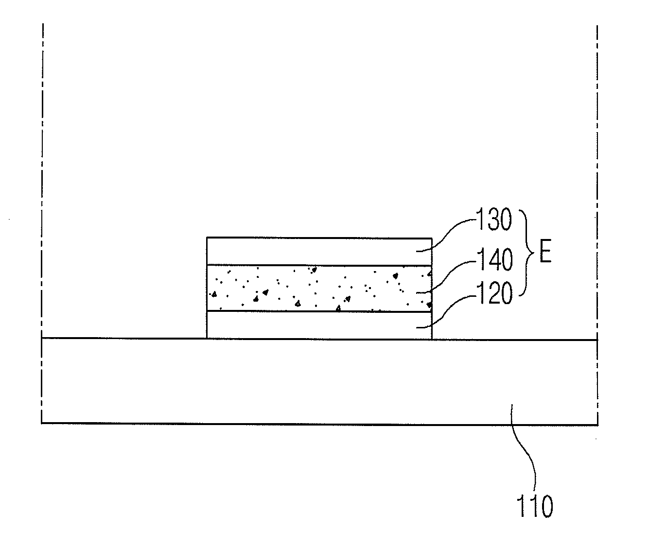
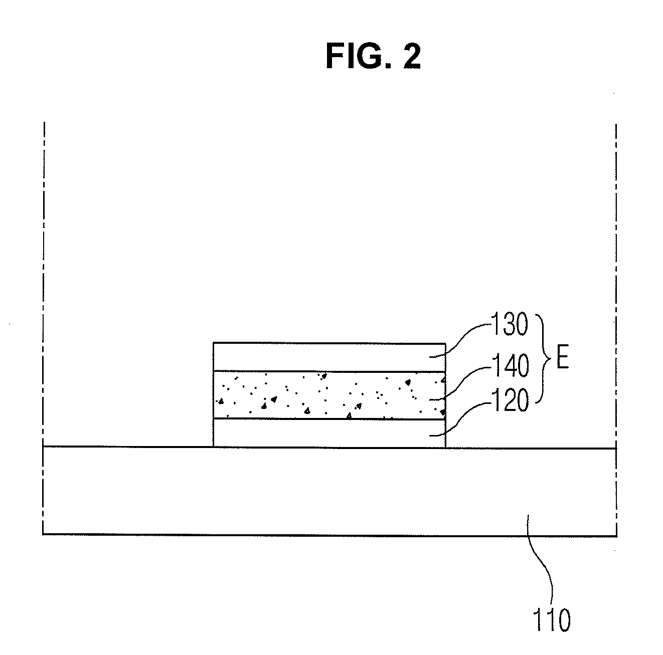
[0036]An indium-tin-oxide (ITO) layer is patterned on a substrate and washed such that an emission area of the ITO layer is 3 mm*3 mm. The substrate is loaded in a vacuum chamber, and the process pressure is adjusted to 1*10−6 ton. CuPC (about 200 angstroms), 4,4′-bis[N-(1-naphtyl)-N-phenylamino]-biphenyl (NPD) (about 400 angstroms), an emitting layer (about 200 angstroms) including aluminum(III) bis(2-methyl-8-quinolinato)-4-phenylphenolate (BAlq) and

in the above Formular 4 as a dopant (about 5 weight %), Alq3 (about 300 angstroms), fluorolithium (LiF) (about 5 angstroms) and aluminum (Al) (about 1000 angstroms) are sequentially formed on the ITO layer such that an OELD is fabricated.

[0037]The OELD produces a brightness of 1682 cd / m2 at an electric current of 0.9 mA and a voltage of 6.2 V. At this time, the X index and Y index of CIE color coordinates are 0.641 and 0.357, respectively.

example 2

[0038]An ITO layer is patterned on a substrate and washed such that an emission area of the ITO layer is 3 mm*3 mm. The substrate is loaded in a vacuum chamber, and the process pressure is adjusted to 1*10−6 ton. CuPC (about 200 angstroms), NPD (about 400 angstroms), an emitting layer (about 200 angstroms) including BAlq and

in the above Formula 4 as a dopant (about 5 weight %), Alq3 (about 300 angstroms), LiF (about 5 angstroms) and Al (about 1000 angstroms) are sequentially formed on the ITO layer such that an OELD is fabricated.

[0039]The OELD produces a brightness of 1850 cd / m2 at an electric current of 0.9 mA and a voltage of 6.0 V. At this time, the X index and Y index of CIE color coordinates are 0.642 and 0.357, respectively.


PUM

PropertyMeasurementUnit
voltageaaaaaaaaaa
thicknessaaaaaaaaaa
thicknessaaaaaaaaaa

Abstract

A red phosphorescent compound includes a host material being capable of transporting an electron or a hole; and a dopant material represented by following Formula 1:and each of R1 to R4 is one of the group consisting of hydrogen atom (H), C1 to C6 substituted or non-substituted alkyl group, C1 to C6 substituted or non-substituted alkoxy group, and halogen atom.

Description

RELATED APPLICATIONS[0001]The present application claims the benefit of Korean Patent Application No. 10-2008-0120419 filed in Korea on Dec. 1, 2008, which is hereby incorporated by reference in its entirety.BACKGROUND[0002]1. Field of the Disclosure[0003]The present disclosure relates to a red phosphorescent compound and an organic electroluminescent device (OELD) and more particularly to a red phosphorescent compound having high color purity and high luminescent efficiency and an OELD using the red phosphorescent compound.[0004]2. Discussion of the Related Art[0005]Recently, the demand for a flat panel display device having a relatively large display area and a relatively small occupancy has increased. Among the flat panel display devices, an OELD has various advantages as compared to an inorganic electroluminescent device, a liquid crystal display device, a plasma display panel, and so on. The OELD device has excellent characteristics with respect to view angle, contrast ratio an...

Claims


Application Information

Patent Timeline
Patent Type & Authority Applications(United States)
IPC IPC(8): H01L51/50C09K11/06
CPCY10S428/917C09K11/06C09K2211/1007C09K2211/1011C09K2211/1029C07F15/0006H01L51/0081H01L51/0085H01L51/5016H05B33/10C09K2211/185H10K85/324H10K85/342H10K50/11H10K2101/10H10K85/381H10K85/6572H10K59/123
Inventor KIM, DO HANPARK, CHUN GUNBIN, JONG KWANLEE, KYUNG HOONJEONG, HYUN CHEOLYOO, DONG HEECHO, NAM SUNGPARK, JONG-HYUNPARK, TAE HANCHA, SOON WOOKLEE, SEUNG JAESONG, IN BUMKIM, JUNG KEUN
Owner LG DISPLAY CO LTD
Why Eureka
Try Eureka