

Opto-Electrical Devices and Methods of Making the Same
- Summary
- Abstract
- Description
- Claims
- Application Information
AI Technical Summary
Benefits of technology
Problems solved by technology
Method used
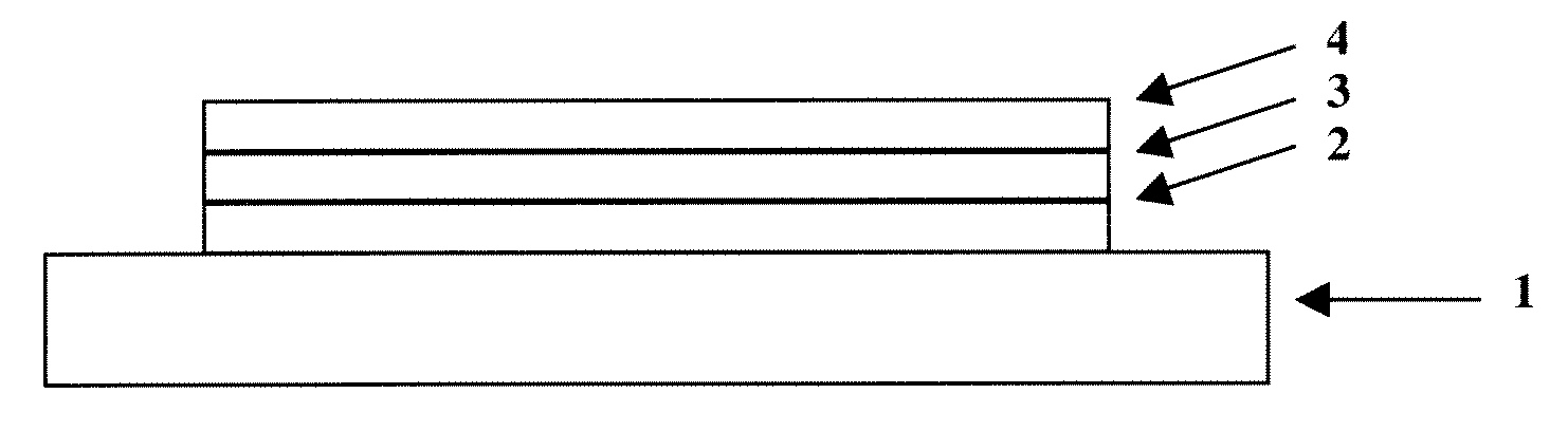
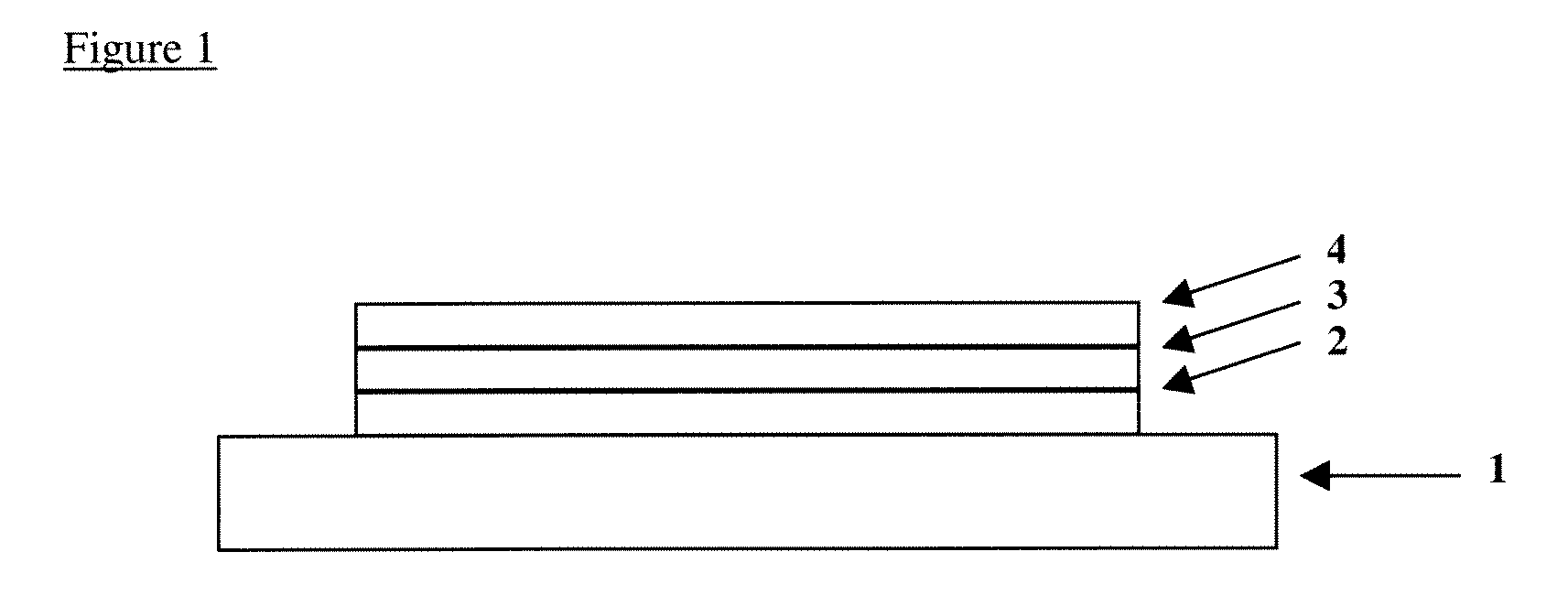
Image

Examples
example
[0113]In the case of an interpenetrating network, a simple example would be two differently functionalised polymers. Polymer A may be a charge transporting polymer containing, for example, a fluorene type monomer unit, a triaryl amine unit (such as TFB) and a vinyl functionalised monomer unit. Polymer B may be an emissive polymer or a different charge transporting polymer, again, for example, based on fluorene. Some of the monomer units may be functionalised with a BOB unit.
[0114]Example structures are shown below:
[0115]The polymers can be synthesised by Pd catalysed Suzuki coupling in toluene using a organic base:
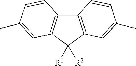
[0116]The following monomers can be used for the first hole transporting polymer layer:
[0117]R can be alkyl, C8H17.
[0118]A typical formulation of this polymer is: X=0.5, Y=0.425, Z=0.075
[0119]The second emitting polymer can be made from the following monomers using the same method:
[0120]A possible formulation here would be: X=0.5, Y=0.4, Z=0.1
[0121]These two materials may ...
PUM
| Property | Measurement | Unit |
|---|---|---|
| Temperature | aaaaa | aaaaa |
| Polarity | aaaaa | aaaaa |
| Concentration | aaaaa | aaaaa |
Abstract
Description
Claims
Application Information