Contact-less power and signal transmission device for a high power level transformer

a transformer and contactless technology, applied in the field of transformers, can solve the problems of reduced reliability, frequent maintenance problems, special challenges of the transformer, etc., and achieve the effects of preventing heat build-up, ensuring safety, and ensuring reliability

Inactive Publication Date: 2010-06-17
DUNLAP GREGORY M +4
View PDF7 Cites 43 Cited by
  • Summary
  • Abstract
  • Description
  • Claims
  • Application Information

AI Technical Summary

Benefits of technology

[0017]Yet another object of the present invention is to provide more efficient signal transmission for control circuits in a rotary transformer. A feature of the present invention is the use of contact-less signal transmission. An advantage of the present invention is that high speed, trouble-free signal transmission between the rotor and the stator is accomplished in a turbine with rotor rpms as high as 1000.
[0018]Still another object of the present invention is to provide a rotary transformer which integrates power transmission and signal transmission features. A feature of this invention is the use of resin-encapsulated stator and rotor windings together with contactless power transmission and contactless signal transmission in power transfer systems whereby power levels as high as 1000 kilowatts are accommodated. An advantage of this invention is the application of water-, steam-, and wind-turbines to accommodate a myriad of operating conditions while preventing heat build-up within the rotor windings, to accumulate currents as high as 1000 Amps.
[0019]Another object of the present invention is to provide a rotary transformer which can accommodate power loads in excess of 1000 kilowatts by optimizing heat transfer from its windings. A feature of this invention is a plurality of segmented winding cavities each having a configuration which facilitates thermal conduction away from the longitudinally-extending surfaces of each of the wires that comprise the winding. An advantage of this feature is more efficient heat conduction away from the windings. Another advantage of this feature is a reduction in magnetic leakage.
[0020]In brief, the present invention provides a transformer that combines the advantages of contact-less power transmission and contact-less signal transmission with enhanced cooling of the current windings. The invented transformer can accommodate power levels up to 1 megaWatt and operate typically in the 10 kW to 100 kW range. An embodiment of the invented rotary transformer comprises: a stationary member comprising a first mechanical carrier with first windings thereupon; a rotary member comprising a second mechanical carrier with second windings thereupon, said rotary member in registration with said stationary member; and segmented highly permeable magnetic material disposed circumferentially on said carriers so as to form channels adapted to receive said windings, whereby said first and second windings and said magnetic material are affixed to said mechanical carriers with a high thermal conductivity resin.
[0021]The present invention also provides a rotary transformer comprising: a stationary member comprising a first mechanical carrier with first windings thereupon; a rotary member comprising a second mechanical carrier with second windings thereupon said rotary member in registration with said stationary member; segmented highly permeable magnetic material disposed circumferentially on said carriers so as to form channels adapted to receive said windings wherein said first and second windings and said magnetic material are affixed to said mechanical carriers with a high thermal conductivity resin; a power supply connected to the first windings with inductive coupling between first windings and second windings such as to induce a current in the second windings; one or more signal transmitters on the stationary member in close proximity to appropriate receivers on the rotating member; and one or more signal transmitters on the rotating member in close proximity to appropriate receivers on the stationary member such that said transmitters and receivers exchange signals in a contact-less manner.
[0022]Furthermore the present invention provides a wind turbine including a rotary transformer comprising: a stationary member with first windings thereupon; a rotary member with second windings thereupon, said rotary member in registration with said stationary member, whereby one or more of said windings are embedded in a high thermal conductivity resin; a power supply connected to the first windings together with inductive coupling between first windings and second windings such as to induce a current in the second windings; one or more signal transmitters on the stationary member in close proximity to appropriate receivers on the rotating member; and one or more signal transmitters on the rotating member in close proximity to appropriate receivers on the stationary member such that said transmitters and receivers exchange signals in a contact-less manner.

Problems solved by technology

This paradigm presents special challenges.
These are prone to reduced reliability, frequent maintenance problems, and the generation of electrical noise that can interfere with, or damage, sensitive electronics.
Oxidation and environmental agents, such as water, ice, and dust, have adverse effects on brush / slip-ring power transmission.
Eliminating brush / slip-ring mechanisms may ameliorate some of the problems associated with operations in environmentally-harsh situations.
However, the state of the art of contactless electrical systems is also lacking as to data processing speed and reliability for the monitoring and control of power transmission, mechanical operating conditions (e.g. the pitch of the wind turbine blades), and temperature of the system components.
Also, state of the art rotary transformers experience high temperatures in their windings that reduce power output and cause damage to the transformer.

Method used


Image

  • Contact-less power and signal transmission device for a high power level transformer
  • Contact-less power and signal transmission device for a high power level transformer
  • Contact-less power and signal transmission device for a high power level transformer

Examples


Embodiment Construction

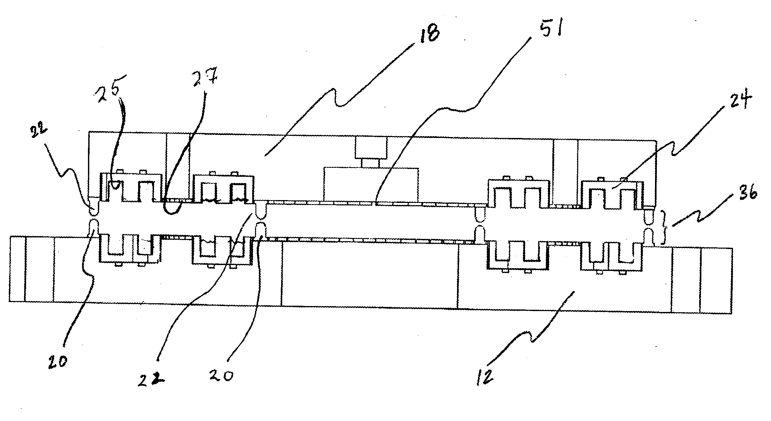
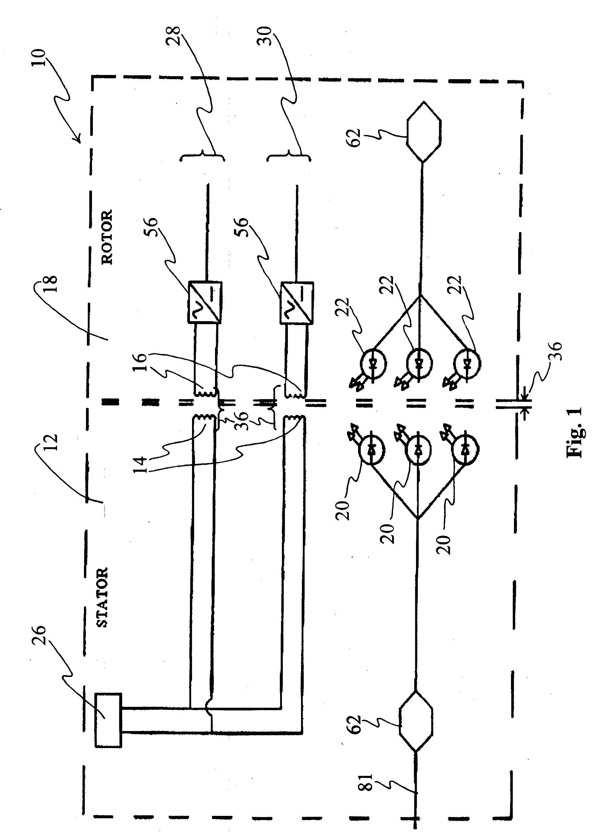
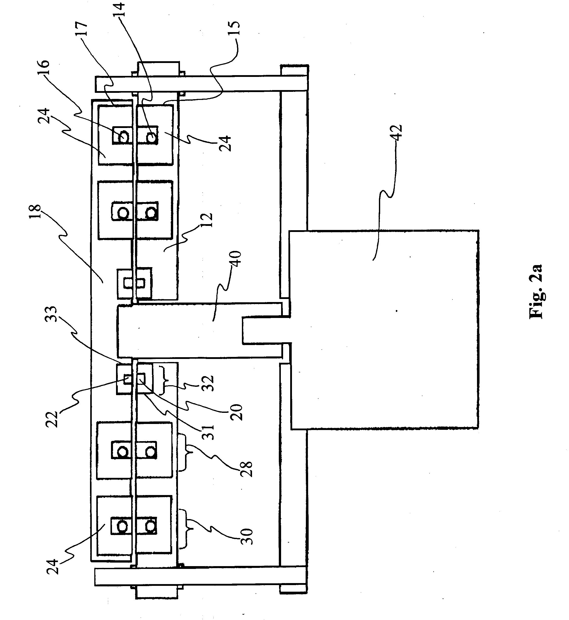
[0032]The present invention discloses a device and a method to be used in conjunction with high power (more than 1,000 kW) electric generation and transmission, including applications involving the use of stationary or rotary transformers where power and signals must be transferred to or from a stationary or a mobile platform (e.g. high-power transformers, motors, generators, turbines, CAT-scan devices, etc.) One especially important area of application of the present invention is electrical power transfer from stator to rotor for wind-power turbines. Another promising application is “micro-turbines,” especially “micro-hydro turbines” that employ running water to provide power to a home or a running stream to provide power at a remote location. In general, the present invention facilitates power transfer under conditions that require the use of compact precisely-controlled rotary transformers.

[0033]A contactless power transfer system is provided comprising a primary member with stro...


PUM

PropertyMeasurementUnit
frequencyaaaaaaaaaa
voltageaaaaaaaaaa
poweraaaaaaaaaa

Abstract

A transformer is provided comprising a first member upon which a first circuit is wound; a second member upon which a second circuit is wound such that power is transferred to the second circuit in a contact-less manner; and a signal transmitter on the first member in close proximity to an appropriate receiver on the second member together with a signal transmitter on the second member in close proximity to an appropriate receiver on the first member such that said transmitters and receivers exchange signals in a contact-less manner, whereby the circuits are embedded in a high thermal conductivity resin. An exemplary embodiment of the invented transformer is one where the second member rotates relative to the first member.

Description

BACKGROUND OF THE INVENTION[0001]1. Field of the Invention[0002]This invention relates to an improved transformer, and more particularly, this invention relates to a transformer featuring bi-directional and contact-less signal and high level power transmission.[0003]2. Background of the Invention[0004]Windmills, wind turbines, and other wind-actuated power devices may utilize a rotary transformer that comprises one or more rotors and stators positioned at the top of a mast or tower.[0005]This paradigm presents special challenges. Both the stator and especially the rotor must be small in bulk. Also, the rotor rotates at a high rate around a horizontal axis. Both the stator windings must be able to carry large currents. So, it is imperative that effective cooling be provided thereto. Also, it is imperative that the rotary transformer be able to withstand extreme weather conditions.[0006]State of the art wind turbine systems use contacting brush and slip ring mechanisms to provide powe...

Claims


Application Information

Patent Timeline
Patent Type & Authority Applications(United States)
IPC IPC(8): H02P9/04H01F27/00
CPCH02P13/10H01F38/18
Inventor DUNLAP, GREGORY M.CHAN, KAI CHIKATCHA, JASON S.SPENGLER, THOMAS A.MILLER, JEREMY A.
Owner DUNLAP GREGORY M
Why Eureka
Try Eureka