Methods for producing an antireflection surface on an optical element, optical element and associated optical arrangement

a technology of anti-reflection surface and optical element, which is applied in the direction of printing, instruments, lighting and heating apparatus, etc., can solve the problems of remaining metal particles being easily diffused out and precipitated at undesirable locations, and achieve good reflection reduction effect, and good reflection reduction

Inactive Publication Date: 2010-06-17
CARL ZEISS SMT GMBH
View PDF4 Cites 87 Cited by
  • Summary
  • Abstract
  • Description
  • Claims
  • Application Information

AI Technical Summary

Benefits of technology

[0022]In a particularly advantageous variant sub-lambda structures are produced with a structural width of 100 nm or less, preferably of 80 nm or less. Sub-lambda structures comprising a structural width in particular of below 80 nm are suitable for reducing reflections of surfaces even at high angles of incidence of up to 50° or up to 70°. The shape of the sub-lambda structures is not limited to pyramid structures or conical structures, for example it is also possible to form hemispherical sub-lambda structures in order to approximate an ideal gradient coating. However, structures with steeply dropping flanks, e.g. cuboid structures, should be avoided in order to ensure a continuous transition of the refractive index between the surface of the optical element and the surrounding medium.
[0023]In a further advantageous variant the sub-lambda structures are produced with a structural height of 100 nm or more, preferably of 180 nm or more, particularly preferably of 240 nm or m

Problems solved by technology

Thus the use of materials that are non-transparent to the useful light, for example metals, as coating materials is associated with a disadvantage in that the incident light is partly absorbed by the metal particles that remain on the surface after etching, which partly counteracts the desired effect, namely to achieve the best possible light yield with the antireflection surf

Method used


Image

  • Methods for producing an antireflection surface on an optical element, optical element and associated optical arrangement
  • Methods for producing an antireflection surface on an optical element, optical element and associated optical arrangement
  • Methods for producing an antireflection surface on an optical element, optical element and associated optical arrangement

Examples


Embodiment Construction

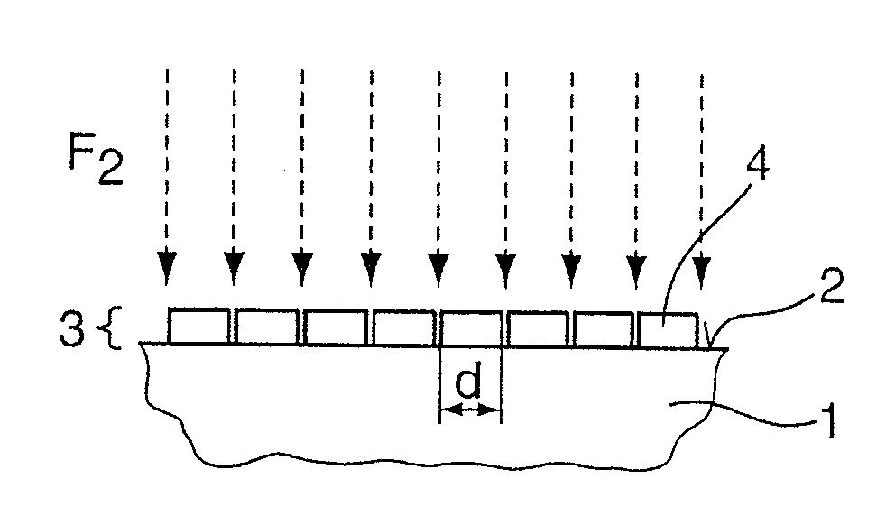
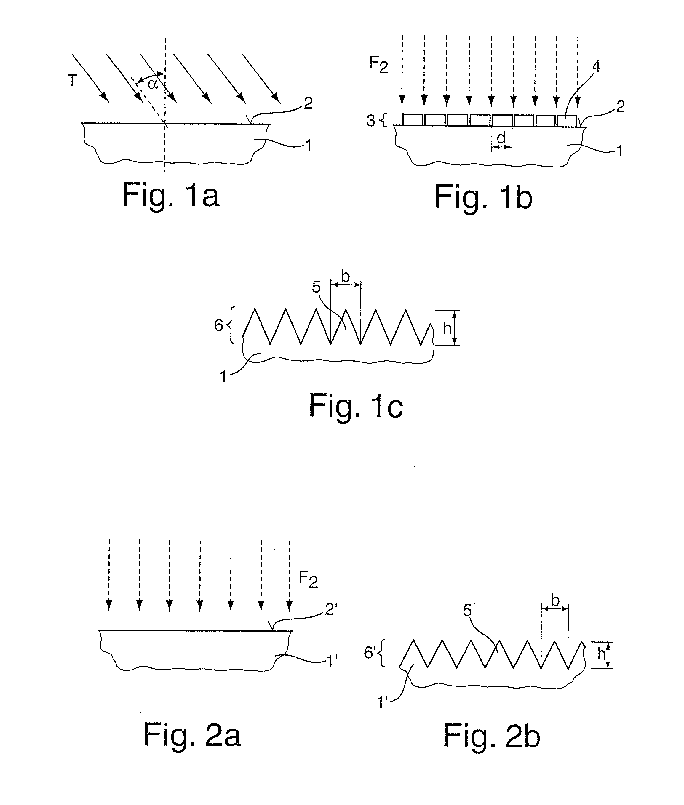
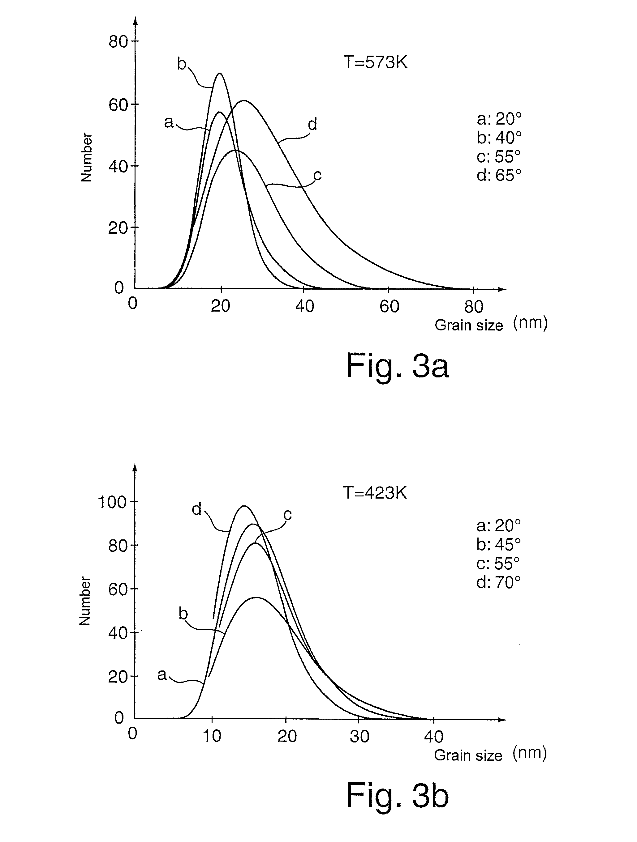
[0033]FIGS. 1a-c show several method-related steps for producing an antireflection surface on an optical element 1 made of fused silica (SiO2), of which element 1 in each case only a partial region is shown in a sectional view in FIGS. 1a-c. In the present case the optical element 1 is a terminating plate for a projection lens (not shown) of a projection exposure apparatus for microlithography. The projection lens and thus also the optical element 1 are operated at a useful-light wavelength λ, of 193 nm.

[0034]In order to produce the antireflection surface, as shown in FIG. 1a, in a first step magnesium fluoride (MgF2) is vapor deposited onto the optical element 1 at a coating temperature T of 573 K, wherein the magnesium fluoride is applied at an angle of incidence of α=20° on a surface 2 of the optical element 1, which surface 2 is to be coated, at a suitable vapor deposition rate (arrows in FIG. 1a), where it forms a coating 3 as shown in FIG. 1b. The magnesium fluoride coating ha...


PUM

PropertyMeasurementUnit
Temperatureaaaaaaaaaa
Pressureaaaaaaaaaa

Abstract

Methods for producing an antireflection surface (6) on an optical element (1) made of a material that is transparent at a useful-light wavelength λ in the UV region, preferably at 193 nm. A first method includes: applying a layer (3) of an inorganic, non-metallic material, which forms nanostructures (4) and is transparent to the useful-light wavelength λ, onto a surface (2) of the optical element (1); and etching the surface (2) while using the nanostructures (4) of the layer (3) as an etching mask for forming preferably pyramid-shaped or conical sub-lambda structures (5) in the surface (2). In a second method, the sub-lambda structures are produced without using an etching mask. An associated optical element (1) includes such an antireflection surface (6), and an associated optical arrangement includes such an optical element (1).

Description

CROSS-REFERENCE TO RELATED APPLICATIONS[0001]This is a Continuation of International Application PCT / EP2008 / 003987, with an international filing date of May 19, 2008, which was published under PCT Article 21(2) in English, and the complete disclosure of which, including amendments, is incorporated into this application by reference; this application also claims the benefit under 35 U.S.C. 119(e)(1) of U.S. Provisional Application No. 60 / 942,157, filed Jun. 5, 2007. The disclosure of U.S. Provisional Application No. 60 / 942,157, filed Jun. 5, 2007, is considered part of and is incorporated by reference in the disclosure of the present application.FIELD OF THE INVENTION[0002]The invention relates to methods for producing an antireflection surface on an optical element, to an optical element comprising an antireflection surface, as well as to an optical arrangement comprising at least one optical element having such an antireflection surface.[0003]Reducing reflections on surfaces of opt...

Claims


Application Information

Patent Timeline
IPC IPC(8): G03B27/72G02B1/11B05D5/06
CPCG02B1/118
Inventor ZACZEK, CHRISTOPHFEDOSENKO, GENNADYHENSCHEL, WOLFGANGKRAEHMER, DANIEL
Owner CARL ZEISS SMT GMBH
Why Eureka
Try Eureka