
Carbonitriding method, machinery component fabrication method, and machinery component

a technology of carbonitriding and machinery components, which is applied in the direction of manufacturing tools, furnaces, heat treatment equipment, etc., can solve the problems of increasing production costs, difficult to render the quality of the workpiece stable, and difficulty in directly measuring the amount of nitrogen permeating into the surface layer of the workpiece, so as to improve reduce the fabrication cost. , the effect of improving the nitrogen permeation ra

Active Publication Date: 2010-06-24
NTN CORP
View PDF1 Cites 29 Cited by
  • Summary
  • Abstract
  • Description
  • Claims
  • Application Information

AI Technical Summary

Benefits of technology

[0007]However, conventional carbonitriding process methods including the aforementioned carbonitriding method based on the undecomposed ammonia concentration as a parameter are disadvantageous in that the permeating rate of nitrogen into the workpiece (the amount of nitrogen permeating into the surface of the workpiece per unit area per unit time) cannot be readily controlled. The carbonitriding process is one step that is relatively high in cost in the fabrication steps of a machinery component. Therefore, there is a demand for reducing the cost of the carbonitriding process. This demand can be met if the permeating rate of nitrogen can be increased to improve the efficiency of the carbonitriding process by controlling the permeating rate of nitrogen to the workpiece.

Problems solved by technology

It is difficult to directly measure the amount of nitrogen permeating into the surface layer of the workpiece during the carbonitriding process.
It is therefore difficult to render the quality of the workpiece stable until the optimum ammonia gas flow rate is determined.
Moreover, since the trial and error must be carried out at the production line, workpieces that do not meet the required quality will be produced, leading to the possibility of increasing the production cost.

Method used


Image

  • Carbonitriding method, machinery component fabrication method, and machinery component
  • Carbonitriding method, machinery component fabrication method, and machinery component
  • Carbonitriding method, machinery component fabrication method, and machinery component

Examples


example 1

[0094]Example 1 of the present invention will be described hereinafter. An experiment to study the relationship between the α value defined by equation (2) and the permeating amount of nitrogen into the workpiece was carried out. The procedure of the experiment is set forth below.

[0095]The capacity of the heat treatment furnace employed for the experiment was 120 L (liter). The workpiece was a JIS SUJ2 (1 mass % of carbon content) ring having an outer diameter of φ38 mm, an inner diameter of φ30 mm, and a width of 10 mm. This ring of 101 g (gram) was placed in the heat treatment furnace. A heating pattern similar to that of FIG. 10 was employed, and the retention temperature of carbonitriding was 850° C. The permeating amount of nitrogen into the workpiece was measured with the ac*, undecomposed ammonia amount, carbonitriding time, and composition of base gas (atmosphere gas other than enriched gas and ammonia gas) in the atmosphere varied. The amount of nitrogen permeating into the...


PUM

PropertyMeasurementUnit
Percent by massaaaaaaaaaa
Massaaaaaaaaaa
Temperatureaaaaaaaaaa

Abstract

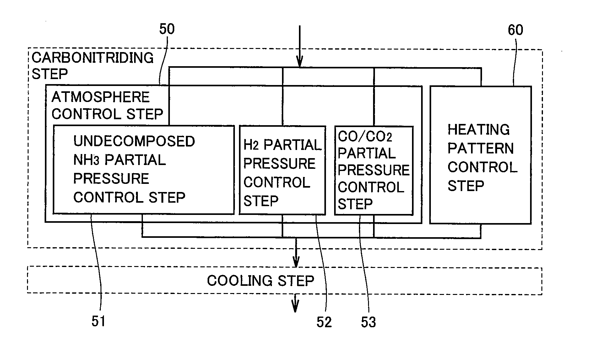
A carbonitriding method that can improve the nitrogen permeating rate to render the carbonitriding process effective includes an atmosphere control step (50), and a heating pattern control step (60). The atmosphere control step (50) includes an undecomposed NH3 partial pressure control step (51), and a CO / CO2 partial pressure control step (53). The undecomposed NH3 partial pressure control step (51) and the CO / CO2 partial pressure control step (53) are carried out in the atmosphere control step (50) such that ac* defined by the following equation (1) is at least 0.88 and not more than 1.27, and α defined by equation (2) is at least 0.012 and not more than 0.020, where PN is the undecomposed ammonia partial pressure and PH is the hydrogen partial pressure in the heat treatment furnace, whereinac*=(Pco)2K×Pco2(1)PCO: partial pressure of carbon dioxide (atm), PCO<sub2>2< / sub2>: partial pressure of carbon dioxide (atm)K: equlibrium constant at <C>+CO22COα=PN0.006×(PH)32×(1.877-1.055×ac*)100(2)

Description

TECHNICAL FIELD[0001]The present invention relates to a carbonitriding method, a fabrication method of a machinery component, and a machinery component. More particularly, the present invention relates to a carbonitriding method for carbonitriding a workpiece formed of steel that contains at least 0.8 mass % of carbon, a fabrication method of a machinery component including the step of carbonitriding a workpiece formed of steel that contains at least 0.8 mass % of carbon, and a machinery component formed of steel that contains at least 0.8 mass % of carbon, subjected to carbonitriding.BACKGROUND ART[0002]Generally in a carbonitriding process, particularly in a gas carbonitriding process applied to a workpiece formed of steel, the atmosphere in a heat treatment furnace is controlled by introducing RX gas and ammonia (NH3) gas into the heat treatment furnace at a constant flow rate (supplied amount), and controlling the carbon potential (CP) value in the heat treatment furnace based o...

Claims


Application Information

Patent Timeline
IPC IPC(8): C23C8/32C22C38/00
CPCC21D1/06C21D1/74C21D1/76C21D9/32C23C8/32C21D9/40C21D11/00C23C8/30C21D9/36F16C33/64
Inventor OHKI, CHIKARA
Owner NTN CORP
Learn More