
Method for Manufacturing Gradient-Index Optical Element Having Infrared Absorbing Ability

Inactive Publication Date: 2010-07-01
ISUZU GLASS +1
View PDF8 Cites 32 Cited by
  • Summary
  • Abstract
  • Description
  • Claims
  • Application Information

AI Technical Summary

Benefits of technology

[0101]According to the method of the invention, an gradient-index optical element having infrared absorbing ability in which a different refractive index region or refractive index distribution from the rest of the substrate is formed in a desired portion of a glass substrate to utilize differences in the refractive index or refractive index distribution can be provided by simply applying a paste containing a specific metal compound to a glass substrate containing an alkali metal component, at least one member selected from the group consisting of iron, copper, cobalt and vanadium, and over 3 wt. % of iron, when contained singly among iron, copper, cobalt and vanadium, on an Fe2O3 basis, taking the total weight of the glass as 100 wt. %, and heating the substrate in an atmosphere such as air. This method enables the production of an optical element at low cost without requiring a complicated production process.
[0102]Moreover, since the method does not use a molten salt, strict control over a molten salt is not necessary, and the heat treatment temperature and the metal compound concentration in the paste can be controlled independently. Furthermore, unlike immersion in a molten salt, since the paste is applied to a desired portion of the substrate, it is not necessary to mask the substrate surface with a blocking film, etc.

Problems solved by technology

However, in these cameras, the camera lens and the infrared-cut filter are installed separately, limiting the ability to downsize lens peripheral areas.
However, common ion exchange methods have the following problems.
The first problem is the control of conditions of the molten salt at the time of ion exchange.
For this reason, there are cases in which the concentration of ions in the molten salt and the ion exchange temperature cannot be controlled independently.
Therefore, to produce a graded refractive index lens having a desired refractive index distribution by an ion exchange method, it is not easy to select the appropriate ion exchange conditions such as the molten salt composition, temperature, immersion time, etc., and a high level of expertise is needed.
The second problem is the application of an ion exchange-blocking film.
Photolithography technique is generally used to apply an ion exchange-blocking film, but formation of such a blocking film requires a complicated process.

Method used


Image

  • Method for Manufacturing Gradient-Index Optical Element Having Infrared Absorbing Ability
  • Method for Manufacturing Gradient-Index Optical Element Having Infrared Absorbing Ability
  • Method for Manufacturing Gradient-Index Optical Element Having Infrared Absorbing Ability

Examples


example 1

Production of Graded Refractive Index Microlens

[0109]A glass containing 68 wt. % of SiO2, 9 wt. % of CaO, 14 wt. % of Na2O, 1 wt. % of K2O, 1.5 wt. % of Al2O3, 2.4 wt. % of MgO and 3.1 wt. % of Fe2O3 was sized to 10 mm long×10 mm wide×1 mm thick for use as a glass substrate, and the surface thereof was washed.

[0110]A paste of 25 wt. % of AgNO3, 40 wt. % of NaNO3, 15 wt. % of acrylic resin, 15 wt. % of cellulose resin, and 5 wt. % of terpineol (the paste being prepared by mixing 20 parts by weight of organic solvent, 120 parts by weight of resin component, and 160 parts by weight of additive, per 100 parts by weight of silver compound) was applied dropwise using a syringe to one side of the glass to form a circle (diameter: 300 μm) to a thickness of 1 mm.

[0111]Subsequently, the pasted glass substrate was dried at 200° C. for 1 hour, and then heat-treated in air at 300° C. for 3 hours.

[0112]The silver distribution in the heat-treated sample was determined using an EDX (Energy Dispersi...

example 2

Production of Graded Refractive Index Microlens Array

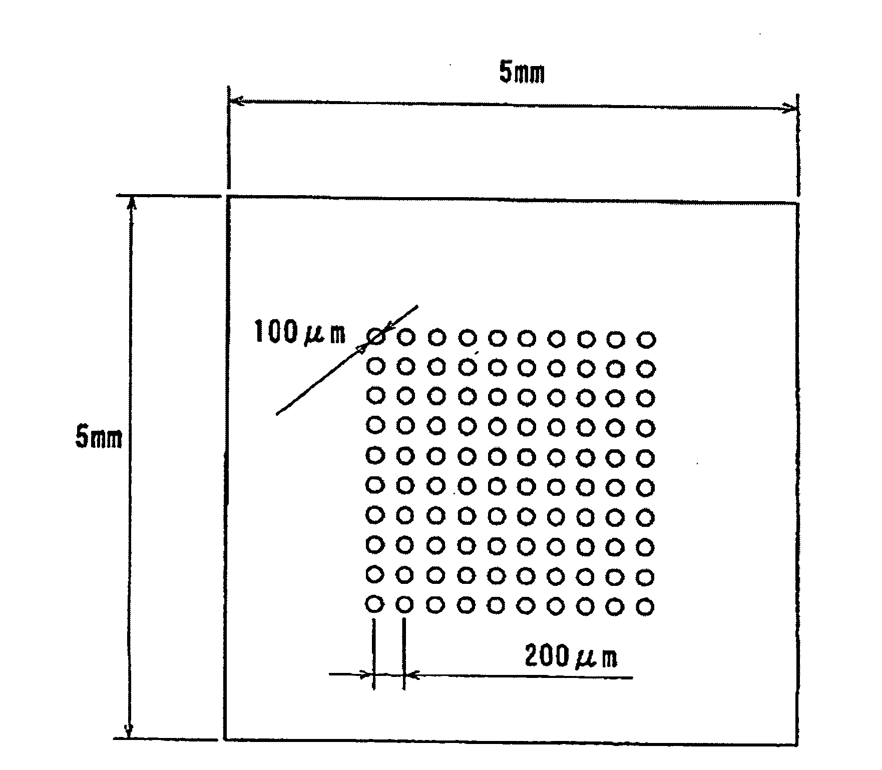
[0116]A glass containing 51 wt. % of P2O5, 18 wt. % of ZnO, 6 wt. % of Al2O3, 5 wt. % of Li2O3, 10 wt. % of Na2O, 3 wt. % of CaO, 3 wt. % of MgO and 4 wt. % of CuO was sized to 5 mm long×5 mm wide×1 mm thick for use as a glass substrate, and the surface thereof was washed.

[0117]To one side of the glass substrate was applied a paste consisting of 25 wt. % of AgNO3, 40 wt. % of NaNO3, 15 wt. % of acrylic resin, 15 wt. % of cellulose resin and 5 wt. % terpineol (the one with 20 parts by weight of organic solvent, 120 parts by weight of resin component and 160 parts by weight of additives, per 100 parts by weight of silver compound; viscosity 10 cP at room temperature) by the ink-jet method to form a circle (diameter 100 μm). The application was performed to form 10 by 10 circles (total 100 dots) with a patterning interval (distance from the center of one circle to the center of the adjacent circle) of 200 μm to a paste thickness of 1...


PUM

PropertyMeasurementUnit
Thicknessaaaaaaaaaa
Infrared transmittanceaaaaaaaaaa
Distributionaaaaaaaaaa

Abstract

A method of readily producing a gradient optical element having infrared absorbing ability by easily forming a refractive index distribution in a desired portion of a glass substrate having infrared absorbing ability without requiring a specific treatment atmosphere nor using a molten salt.More specifically, the present invention provides a method for producing a gradient-index optical element having infrared absorbing ability, the method comprising applying a paste containing an organic resin, an organic solvent, and at least one compound selected from the group consisting of lithium compounds, potassium compounds, rubidium compounds, cesium compounds, silver compounds, copper compounds, and thallium compounds onto a glass substrate containing an alkali metal component, at least one member selected from the group consisting of iron, copper, cobalt and vanadium, and over 3 wt. % of iron, when contained singly among iron, copper, cobalt and vanadium, on an Fe2O3 basis, taking the total weight of the glass as 100 wt. %, and heating the glass substrate at a temperature below the softening temperature of the glass substrate.

Description

TECHNICAL FIELD[0001]The present invention relates to a method for manufacturing a gradient-index optical element having infrared absorbing ability.BACKGROUND ART[0002]The spectral sensitivity of image pickup devices used in photo cameras, VTR cameras, etc., is wide, from the visible light range to the infrared range. For this reason, infrared-cut filters that correct spectral sensitivity to the proximity of human visibility by absorbing the light in the infrared range from 800 to 1,000 nm and permeating the light in the visible light range from 400 to 650 nm are considered to be essential optical components.[0003]Lately, optical instruments have been downsized, and there is high demand for smaller versions of the cameras described above. However, in these cameras, the camera lens and the infrared-cut filter are installed separately, limiting the ability to downsize lens peripheral areas. To solve this problem, attempts have been made to manufacture a camera lens by forming a refrac...

Claims


Application Information

Patent Timeline
IPC IPC(8): G02B3/00B05D5/06
CPCC03C3/17C03C4/082C03C21/008G02B1/00G02B3/0087G02B5/226C03C3/087
Inventor SUETSUGU, TATSUYAKIMURA, KAZUHISAOHTANI, TAKESHIKAGA, NAOKOKIKUCHI, NAOKIYAMASHITA, NAOTOMORIZANE, YUKIKOEINISHI, TOSHIHIKOKADONO, KOHEI
Owner ISUZU GLASS
Learn More