High-voltage pulse generator and high-pressure discharge lamp having such a generator

Inactive Publication Date: 2010-07-08
OSRAM GMBH
View PDF8 Cites 17 Cited by
  • Summary
  • Abstract
  • Description
  • Claims
  • Application Information

AI Technical Summary

Benefits of technology

[0006]It is an object of the present invention to provide a high-voltage pulse generator, t

Problems solved by technology

A disadvantage of this is that the supply leads must be made high-voltage proof.
They were not however widely successful, because on the one hand they are too expensive.
On the other hand, the advantage of building them into the cap is not sufficient, since the problem of feeding the high voltage into the bulb remains.
The likelihood of damage to the lamp, whether insulation problems or breakdown in the cap, therefore increases gre

Method used


Image

  • High-voltage pulse generator and high-pressure discharge lamp having such a generator
  • High-voltage pulse generator and high-pressure discharge lamp having such a generator
  • High-voltage pulse generator and high-pressure discharge lamp having such a generator

Examples


Example

First Embodiment

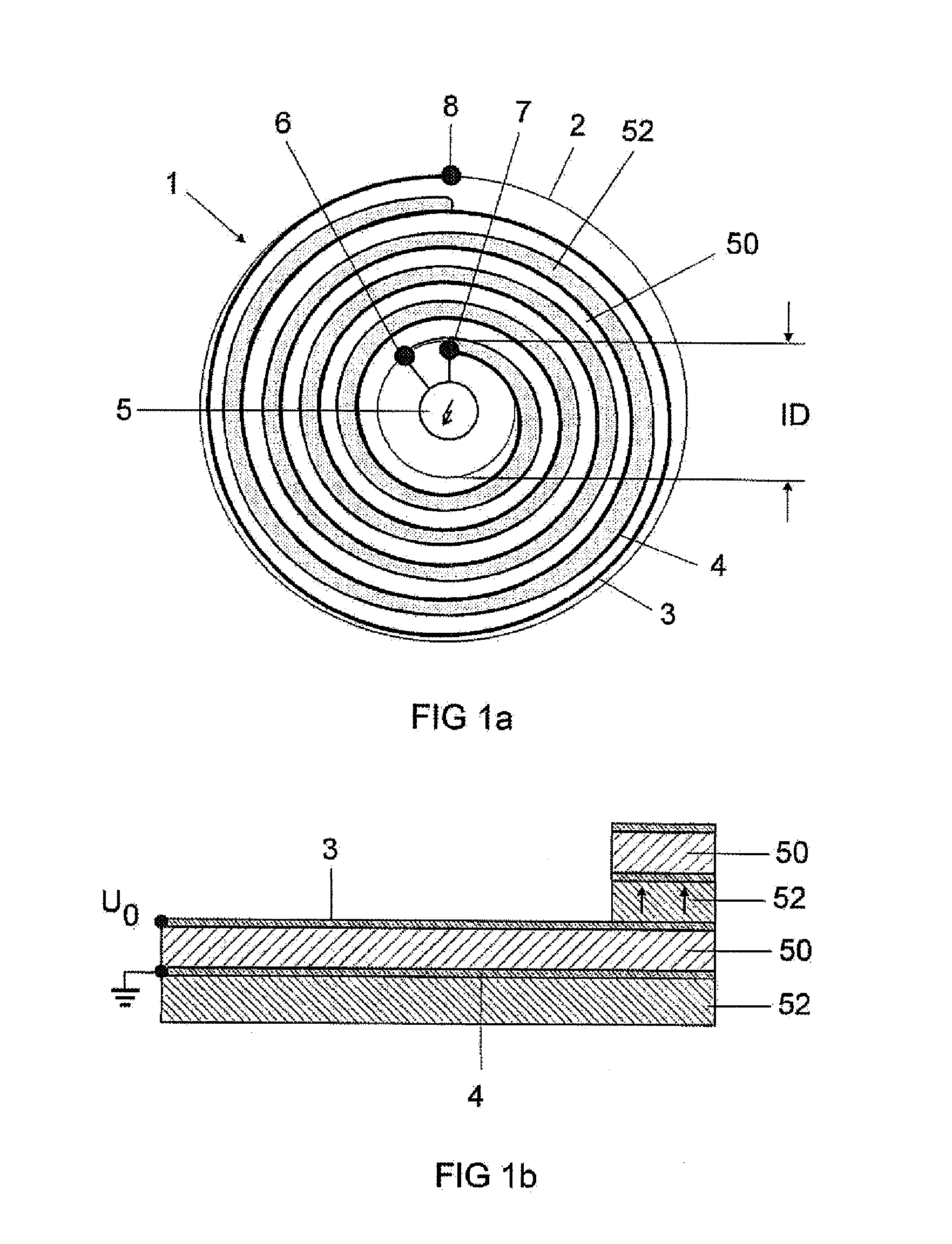
[0047]FIG. 1a shows the structure of the first embodiment of a spiral pulse generator 1 in plan view. It consists of a ceramic cylinder 2, in which two different metal conductors 3 and 4 are wound spirally as a foil composite. The cylinder 2 is internally hollow and has a given internal diameter ID. The two inner contacts 6 and 7 of the two conductors 3 and 4 preferably lie next to one another and are connected together via a spark gap 5. Between the two metal conductors lie the two ceramic sheets, which respectively are used as insulators and are made from different materials. One sheet 50 is made of material with a high ∈, in particular BaTiO3. This sheet acts as the active layer in the spiral pulse generator. The second sheet 52 is made of a material with a high p, in particular Mn / Zn ferrite. This sheet acts as the passive layer in the spiral pulse generator. The active layer in the winding of the spiral pulse generator is preferably the one which is short-circui...


PUM

PropertyMeasurementUnit
Timeaaaaaaaaaa
Diameteraaaaaaaaaa
Pressureaaaaaaaaaa

Abstract

A high-voltage pulse generator is provided. The high-voltage pulse generator may include a spiral pulse generator, the spiral pulse generator being configured as an LTCC component and being wound from at least two ceramic sheets and at least two metal layers, wherein the two ceramic sheets are joined to form a multilayer structure including at least one first layer of a capacitively acting ceramic sheet including a high permittivity of at least ∈r=10 and at least one second layer of an inductively acting ceramic sheet having a high permeability of at least μr=1.5, which are wound together with the metal layers to form a spiral.

Description

TECHNICAL FIELD[0001]The invention relates to a high-voltage pulse generator according to the precharacterizing clause of claim 1. Such generators may in particular be used for high-pressure discharge lamps for general lighting or for photo-optical purposes or for automobiles. The invention furthermore relates to a high-pressure discharge lamp which is equipped with such a generator.PRIOR ART[0002]The problem of igniting high-pressure discharge lamps is currently resolved by integrating the ignition apparatus into the ballast apparatus. A disadvantage of this is that the supply leads must be made high-voltage proof.[0003]In the past, there have repeatedly been attempts to integrate the ignition unit into the lamp. In this context, attempts have been made to integrate it into the cap. Particularly effective ignition, offering high pulses, is achieved by means of high-voltage pulse generators of the spiral generator type. Some time ago, such apparatus were proposed for various high-pr...

Claims


Application Information

Patent Timeline
IPC IPC(8): H01J7/44H03K3/02H02K15/00
CPCH03K3/53Y10T29/49009H05B41/042
Inventor KLOSS, ANDREASSCHALK, BERNHARDWALTER, STEFFEN
Owner OSRAM GMBH
Why Eureka
Try Eureka