Multiscale Optical System

a multi-scale optical system and optical system technology, applied in the field of imaging optics, can solve the problems of reducing system volume, angular resolution and number of resolvable object points, and affecting the optical performance of optical systems, so as to improve optical image resolution, lower cost lens systems, and the effect of improving the resolution of optical images

Active Publication Date: 2010-07-08
APPLIED QUANTUM TECH +1
View PDF18 Cites 137 Cited by
  • Summary
  • Abstract
  • Description
  • Claims
  • Application Information

AI Technical Summary

Benefits of technology

[0011]The present invention enables optical systems that overcome some of the disadvantages of the prior art. The present invention enables a multi-scale lens system in which light collection and light processing functions are separate. As a result, each function can be independently designed without deleterious impact on the other function. The present invention enables lens systems that are characterized by one or more of the following: wide-field imaging with diffraction limited resolution; improved optical image resolution at higher light collection; lower cost lens systems; reduced system mass and volume; 3D imaging capability; improved depth-of-field; and lower cost detection systems. Embodiments of the present invention are particularly suitable for high-performance imaging systems for use in applications such as cell phones, cameras, surveillance systems, teleconferencing systems, satellite systems, and the like.

Problems solved by technology

As these elements shrink, however, the optical performance of their optical systems suffer since the angular resolution and number of resolvable object points both decrease as the diameter of the imaging system is reduced.
The result is reduced system volume; however, the reduction in system volume is achieved at the cost of significant computational post-processing and compromised image quality.
In addition, the design space for multi-aperture cameras is severely restricted, which has limited their adoption in practical systems.
As a result, conventional multi-aperture designs are generally restricted to very small collection apertures.
This also limits the number of camera formats that can be designed.
Further, a multi-aperture camera typically has a restricted field-of-view due to a need to prevent the overlapping of sub-images on the detector array.
Alternatively, absorbing barriers can be placed between the sub-image regions of the detector array; however, this significantly increases manufacturing cost and complexity.

Method used


Image

  • Multiscale Optical System
  • Multiscale Optical System
  • Multiscale Optical System

Examples


Embodiment Construction

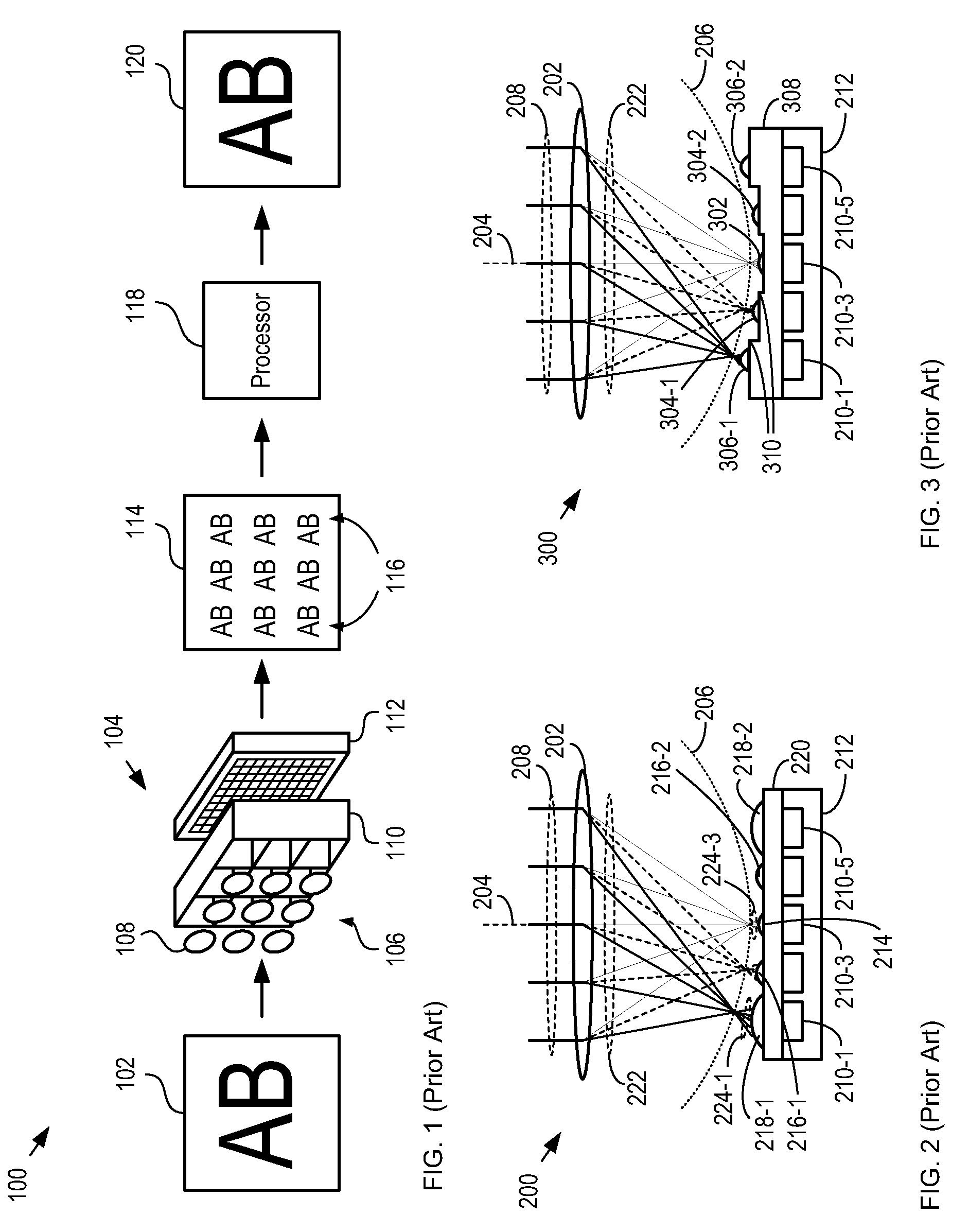
[0030]FIG. 1 depicts a first imaging system in accordance with the prior art. System 100 is an integrated computational imaging system that utilizes a multi-lens array and a reconstruction algorithm to provide high-resolution over a wide field-of-view. System 100 comprises imager 104, and processor 118.

[0031]Imager 104 is a Thin Observation Module by Bound Optics (TOMBO) imager that receives an optical field from scene 102. Imager 104 comprises lens array 106, separation layer 110, and photodetector array 112.

[0032]Lens array 106 comprises a two-dimensional array of substantially identical lenses 108. Each lens 108 in lens array 106 and its corresponding array of photodetectors forms a different imaging unit. Separation layer 110 comprises partitions that mitigate optical crosstalk between the imaging units.

[0033]In operation, imager 104 provides intermediate image 114. Intermediate image 114 comprises a plurality of images 116, each of which is a copy of a low-resolution image of s...


PUM


Abstract

A means of enabling an imaging lens system that overcomes some of the costs and disadvantages of the prior art is disclosed. A lens system in accordance with the present invention reduces or eliminates one or more aberrations of an optical input by separating image collection functionality from image processing functionality. As a result, each function can be performed without compromising the other function. An embodiment of the present invention comprises a collection optic that provides a first optical field, based on light from a scene, to a processing optic that comprises a plurality of lenslets. The processing optic tiles the first optical field into a plurality of second optical fields. Each lenslet receives a different one of the plurality of second optical fields, reduces at least one localized aberration in its received second optical field, and provides the corrected optical field to a different one of plurality of photodetectors whose collective output is used to form a spatially correlated sub-image of that corrected optical field. The sub-images are readily combined into a spatially correlated image of the scene.

Description

CROSS REFERENCE TO RELATED APPLICATIONS[0001]This case claims priority of U.S. Provisional Patent Application U.S. 61 / 142,499, which was filed on Jan. 5, 2009 (Attorney Docket: 524-002US), and which is incorporated herein by reference.FIELD OF THE INVENTION[0002]The present invention relates to imaging optics in general, and, more particularly, to imaging lenses.BACKGROUND OF THE INVENTION[0003]A trend in digital camera systems has been the shrinking of both optical elements and detector arrays. As these elements shrink, however, the optical performance of their optical systems suffer since the angular resolution and number of resolvable object points both decrease as the diameter of the imaging system is reduced.[0004]A digital imaging system provides light from an object or scene to an opto-electronic detector array. Each detector provides an electrical signal whose magnitude is a function of the intensity of the light incident on that detector. As a result, the detector array ena...

Claims


Application Information

Patent Timeline
Patent Type & Authority Applications(United States)
IPC IPC(8): H04N5/225
CPCH04N5/2254G02B3/0056H04N23/55
Inventor BRADY, DAVID JONESHAGEN, NATHAN ADRIANMCCAIN, SCOTT THOMAS
Owner APPLIED QUANTUM TECH
Why Eureka
Try Eureka