Indicators

a technology of indicator device and indicator body, which is applied in the direction of thermometer using mean/integrated value, instruments, heat measurement, etc., can solve the problems of constant reduction of electronic components, prohibitive device and integration cost, etc., and achieves low cost, simple design, and easy manufacturing

Inactive Publication Date: 2010-07-15
EASTMAN KODAK CO
View PDF67 Cites 8 Cited by
  • Summary
  • Abstract
  • Description
  • Claims
  • Application Information

AI Technical Summary

Benefits of technology

[0010]The present invention overcomes the problem of creating a low cost indicator device for use on the packaging of an article of goods. It has a simple design which can be easily fabricated by existing manufacturing methods, for example in an inline roll-to-roll process. No complex opto-electronics are required so the method is sufficiently low cost to allow it to be incorporated in packaging applications. The effect is irreversible, which allows it to be used to create indicators that are triggered by exposure to a stimulus, for example to temperature above a prescribed level and then remain in that state, even when the temperature falls below the prescribed level.
[0011]Since in its simplest implementation all that is required is a channel and a flowable material adjacent to the channel, the invention can be used to create indicators on a wide variety of surfaces, such as the packaging material of an article, or the article itself. Since the channel does not have to be confined to planar surfaces the indicator could be created on a three dimensional surface or object. As the channel is created either in the packaging material or on the object to be packaged itself, the indicator is very thin and does not require an extra substrate on which the indicator has been manufactured to be attached to the packaging material. Furthermore, the cost of extra substrate material is eliminated by using the actual packaging material as the indicator substrate.
[0012]The indicator can be operational from the moment it is created, thus reducing cost and complexity of the device, or if it is preferred, the device can be made operational at a later stage using an activation process which does not require the physical rupturing of barriers and thus avoids extra mechanical parts.
[0013]This invention is particularly suited to low cost manufacture by roll to roll processes, including printing, embossing and punching. Indicators of the present invention can be made directly onto packaging at the time of printing, by using the printing process to deposit the flowable material, embossing processes to make the channels and punching processes to make through holes. Lamination and cutting processes are also well known in the label printing industry and these techniques may also be used to further enhance the performance of indicators of the present invention.
[0014]If the channel is combined with a through-hole, then the flowable material can be located on the inside of the packaging material so as to give a more accurate reading of the temperature inside the packaging. Some control of the time it takes for the liquid to flow along the channel can be achieved by changing the channel width, channel geometry, the surface energy or surface texture of the channel or the viscosity or surface tension of the flowable material. A further benefit of the through-hole geometry is that coloured flowable material deposited on the inside of the packaging material may be obscured from view by the packaging material.
[0015]In addition, the channel or channels can be fabricated into a prescribed pattern to allow the creation of text or images which may be unseen until the flowable material enters the channel. In this way a visual warning may be created that is only visible after the device has been exposed to a prescribed environmental stimulus such as a set temperature, or level of UV light for instance. For security or authenticity verification applications the indication can be done using a flowable material having unique reflective or absorptive properties that are only visible when illuminated with UV or IR light to provide an indication that requires a reader device to verify.

Problems solved by technology

Whilst the cost of electronic components is continually being reduced due to economies of scale and mass manufacture, for many packaging applications the cost of the device and the integration required is still prohibitive.

Method used


Image

  • Indicators
  • Indicators
  • Indicators

Examples


example 1

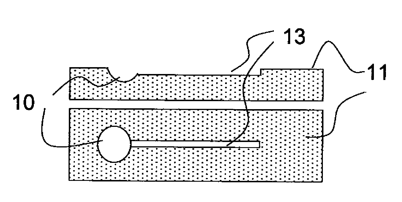
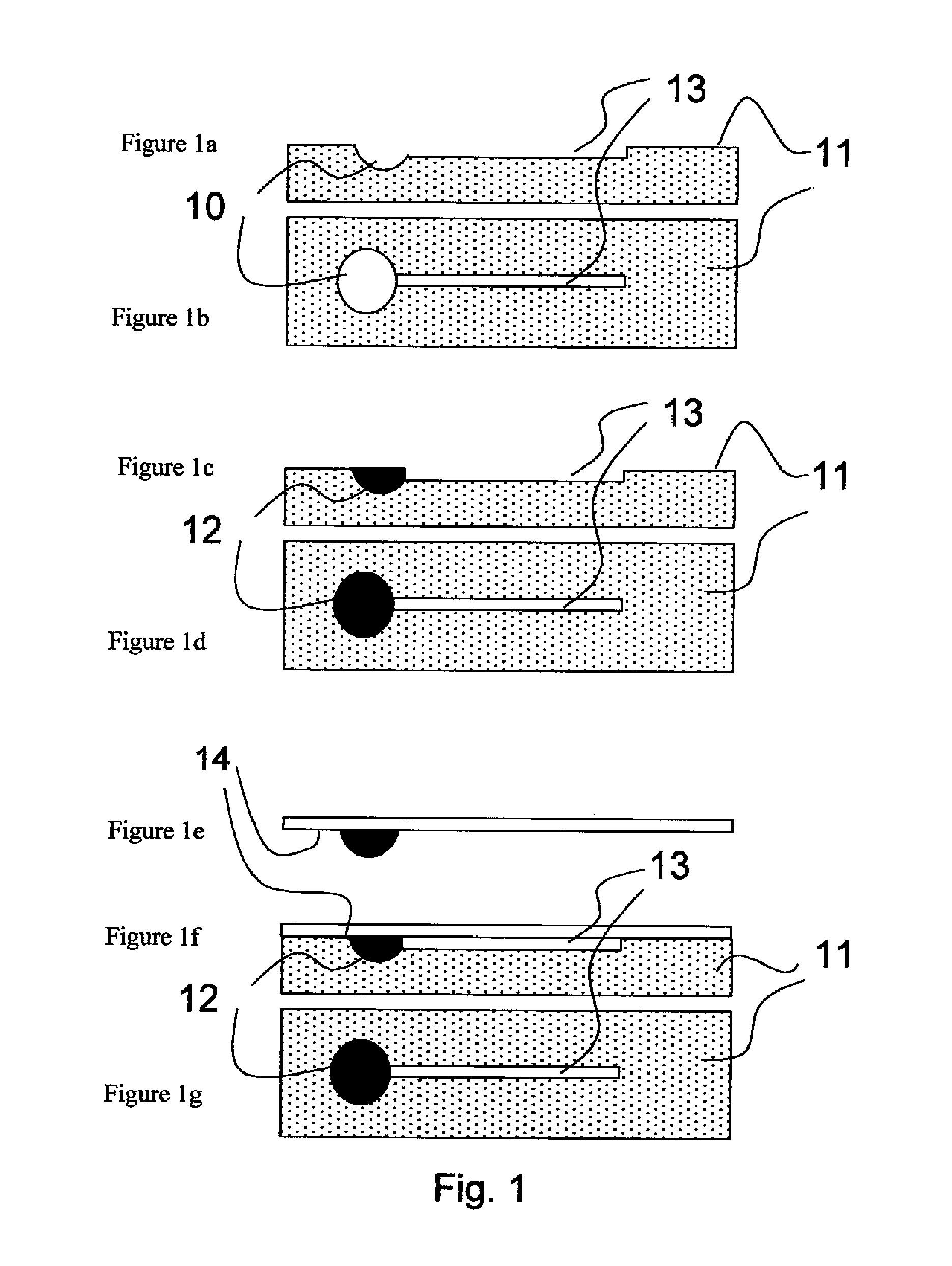
[0043]Embossed channels were created in 100 μm thick PET film, using a circular cutting tool pressed into the substrate. This resulted in a circular channel with a diameter of approximately 10 mm and a ‘V’ shaped cross section with a width of approximately 50 μm. A small section of the channels was filled with eicosane having a low concentration (1-10% w / w) of Sudan Red dye, by pushing a few micrograms of the material into the channels with gentle pressure, the eicosane had a melting point of approximately 38° C., making it possible to locally melt the eicosane to allow channel filling, but prevent flow along the channel. When the substrate was warmed to this temperature the eicosane became mobile and was driven along the channel by capillary forces, thereby creating a circular pattern indicating that the device had been activated by having passed through a temperature threshold of 38° C.

example 2

[0044]Channels were created on a PET substrate or a PE coated paper substrate using photolithography. Both Laminar and SU-8 50 photo-resist were used to create approximately 50 μm thick channels on the substrate. Alkanes with different melting points around 50° C. were used as the flowable indicator. Some oil soluble dye was added to improve visibility. Oil Red, Sudan Red and Oil Blue dyes were found to work well with octadecane, nonadecane and eicosane, by simply adding a small quantity (1-10% w / w) of solid Sudan Red dye to a molten solution of the alkane. SU-8 50 was used in preference to the Laminar resist since it is near transparent, making the unfilled channels difficult to detect on the PET substrate. The resist was spin coated for 30 seconds at 500 rpm followed by 40 seconds at 2000 rpm to result in an approximately 50 μm thick layer. Soft-bake times of approximately 5 minutes at 65° C. and approximately 20 minutes at 95° C. were required to cure properly before exposure. Ex...

example 3

[0045]A sample of 500 μm pitch ‘V’ channels (3M SOLF film) was overcoated with a thin layer of titania 10 to 50 nanometres thick by chemical vapour deposition at 100° C. The titania was then rendered hydrophobic by spin coating 0.3% w / w Fluoroalkyl silane (FAS) in decane, to deposit a thin layer of the FAS on the titania. This increased the sensitivity to UV light since it has been shown that exposure of this layer to UV light causes catalytic destruction of the FAS layer rendering the titania surface hydrophilic. A liquid ink placed on this sample will not wick along the channels until they have been exposed to UV light to make them hydrophilic. In this example a small quantity of aqueous black ink with constituents;

[0046]Water+

[0047]Diethylene glycol—14-22%

[0048]Black colourant 13-14%

[0049]Butoxy tri glycol 10%

[0050]Urea 3-6%

[0051]Triethanolamine 1-3%

was placed into the channels and observed over time. Due to the FAS, the liquid has a large contact angle on the surface of the chan...


PUM

PropertyMeasurementUnit
contact angleaaaaaaaaaa
resonance frequencyaaaaaaaaaa
thickaaaaaaaaaa

Abstract

An indicator device includes a surface provided with at least one channel or at least one through-hole with at least two openings, wherein flowable material in an immobile state is provided adjacent to the channel or adjacent to a first opening of the through-hole, such that after application of a stimulus the material is directed along the channel by the action of capillary forces or into the at least one through-hole by the action of capillary forces and emerges at a second opening, thereby providing an indication of the application of the stimulus.

Description

FIELD OF THE INVENTION[0001]The invention relates to low cost indicator devices, based upon controlled capillary wicking of a liquid, and the manufacture thereof The indicator devices are such that they can be readily integrated into the packaging of an article of goods to serve as an indicator of maximum temperature exposure, light exposure, or authenticity.BACKGROUND OF THE INVENTION[0002]It is often desirable to be able to provide an indication of whether a product has been exposed to undesirable temperature history or UV exposure. This applies to perishable goods such as foods, pharmaceutical products or photographic products which have a limited lifetime that may be shortened by exposure to extreme environmental conditions.[0003]A variety of devices are available to provide this information. These may be divided broadly into two classes, those that contain electronics to enable sensing, display and data recording, and simpler devices which contain no electronics. Whilst the cos...

Claims


Application Information

Patent Timeline
Patent Type & Authority Applications(United States)
IPC IPC(8): G01K1/02
CPCG01K11/08G01K3/04
Inventor BOWER, CHRISTOPHER L.RIDER, CHRISTOPHER B.
Owner EASTMAN KODAK CO
Why Eureka
Try Eureka