Eureka AIR delivers breakthrough ideas for toughest innovation challenges, trusted by R&D personnel around the world.

Interconnecting Microfluidic Package, Fabrication Method and Methods of Use

a technology of microfluidic packaging and fabrication methods, applied in the direction of fluid pressure measurement, liquid/fluent solid measurement, peptides, etc., can solve the problems of inability to meet the needs of major improvements, lack of general, simple and effective packaging techniques, and limited specific applications, etc., to achieve reliable and inexpensive microfluidic packaging

Active Publication Date: 2010-07-15
UNIV OF CENT FLORIDA RES FOUND INC
View PDF30 Cites 23 Cited by
  • Summary
  • Abstract
  • Description
  • Claims
  • Application Information

AI Technical Summary

Benefits of technology

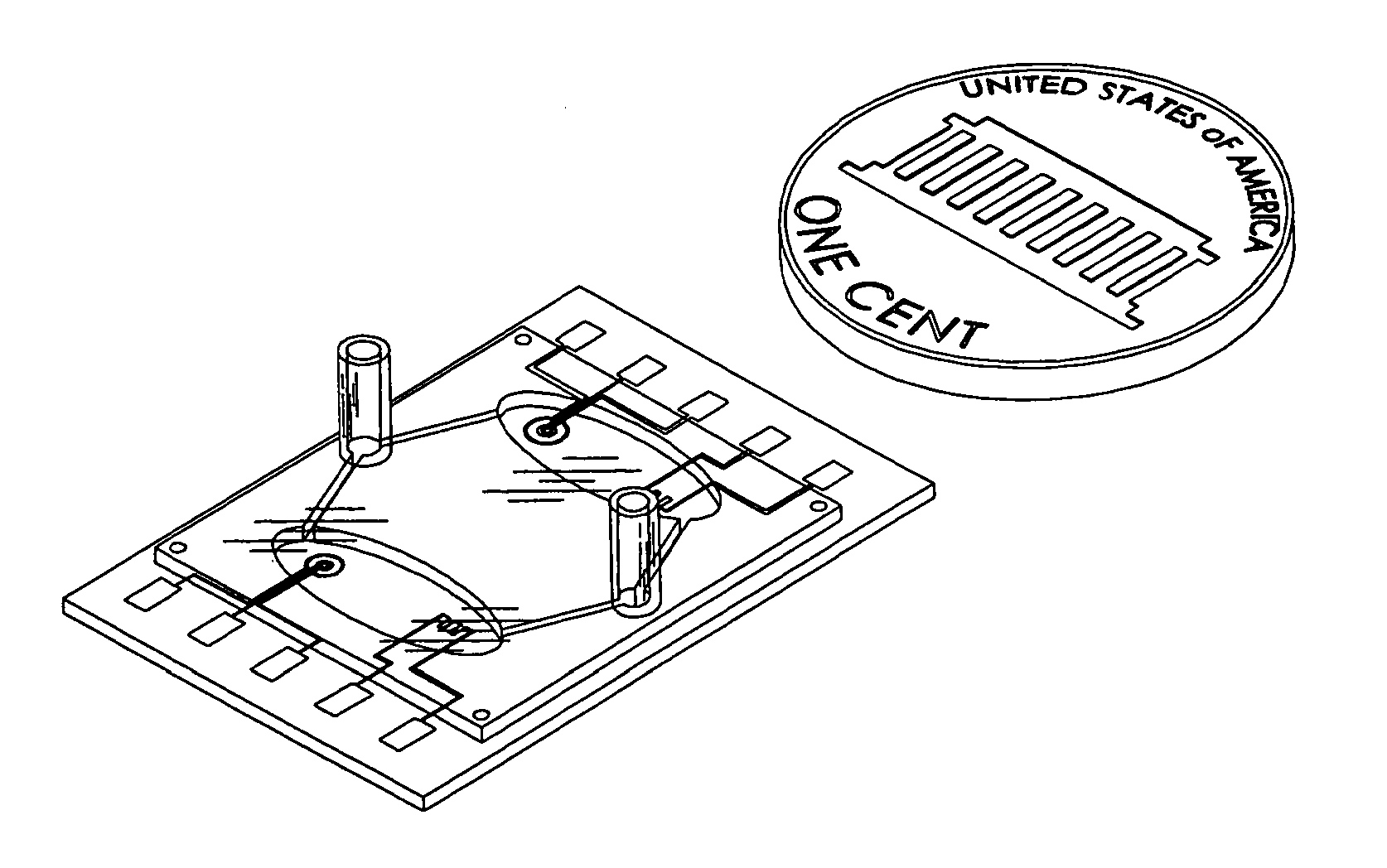
[0012]The first objective of the present invention is to provide a reliable, inexpensive microfluidic package.

Problems solved by technology

The biggest stumbling block to commercial success is the lack of general, simple and effective packaging techniques.
The above references confirm that microfluidic devices, systems and apparatus are available; however, the problems are that the available systems are custom-made with multiple parts, limited to specific applications, expensive and in need of major improvements. C. Gartner et al. discussed one needed improvement which includes standardizing the interfacing of microfluidic devices to the macroworld in “Polymer Based Microfluidic Devices—Examples for Fluidic Interfaces and Standardization Concepts”Proceedings of SPIE—The International Society for Optical Engineering, Vol. 4982, pages 99-104, Jan. 27-29, 2003. C. Gartner et al. provide microfluidic devices with multiple parts that attach to standard devices, such as syring

Method used


Image

  • Interconnecting Microfluidic Package, Fabrication Method and Methods of Use
  • Interconnecting Microfluidic Package, Fabrication Method and Methods of Use
  • Interconnecting Microfluidic Package, Fabrication Method and Methods of Use

Examples


example 1

Chlorine Sensor

[0095]Sensor Design—Using a cost-effective rugged cyclic olefin copolymer (COC) substrate, two layers are designed; a sensor electrode layer and a fluidic layer. For a chlorine sensor, gold (Au), gold (Au) and silver / silver chloride (Ag / AgCl) comprise working, counter and reference electrodes respectively. For a temperature sensor, a meander-type gold (Au) resistor of 1 square millimeter (mm2) was designed. The temperature sensor was included to monitor the sample water temperature and to take into account any thermal effect on the chlorine concentration. The electrode structure and dimensions are shown in FIG. 9. A concentric three electrode design is shown wherein; the outermost curved electrode is the counter electrode (CE) 90 made of a strip of gold (Au) 200 micrometers (μm) in width. The curved working electrode (WE) 92 is spaced 200 μm inside the counter electrode (CE) 90 and is made of a strip of gold (Au) 400 μm in width. The reference electrode (RE) 94 made o...

example 2

Disposable BOD Microsensor

[0106]Sensor Design—As in Example 1, Cyclic Olefin Copolymer (COC) was used as the sensor substrate as well as the material to create the microfluidic layer. It is a rugged, transparent polymer with inertness towards chemicals like acetone, unlike many other plastic materials. Use of the cost-effective COC and batch fabrication techniques allow these sensors to be disposable.

[0107]The BOD sensor 200 consists of 3 layers stacked one above the other as shown in FIG. 21. A bottom electrode layer 220 comprising 2 sets of sensor electrodes222, 223 and one set of temperature sensors 224, 225 are covered with dissolved oxygen selective membrane (not shown). An intermediate microbial layer 226 of yeast T. Cutaneum immobilized on one set of sensor electrodes 222. Microbial stains and sensor structure are very important in the design. Some examples of well-known microbial strains are Rhodococus Erythropolis, Issatchenkia Orientalis and Trichosporon Cutaneum, the cult...


PUM

PropertyMeasurementUnit
response timeaaaaaaaaaa
diameteraaaaaaaaaa
widthaaaaaaaaaa

Abstract

A disposable microsensor is designed, fabricated and tested for standard BOD (Biochemical Oxygen Demand) measurements. A transparent Cyclic Olefin Copolymer (COC) substrate is used for sensor fabrication. Standard lithographic procedures in addition to techniques like screen printing and electroplating are used to fabricate the sensor. A microbial strain of Trichosporon Cutaneum is immobilized over one pair of sensor electrodes while the other is used as a reference. Depending on the respiratory activities of the microbial strain in different samples, the BOD values of the samples can be measured in terms of difference between the output signals. The sensor layer is attached to an injection-molded passive microfluidic channel on the top. Advantages of the BOD microsensor include, but are not limited to, fast BOD measurement, disposability because of its low cost, chemically inert polymer substrate, flow-through sample injection scheme and integration of on-chip optics.

Description

[0001]This is a continuation-in-part of U.S. patent application Ser. No. 11 / 044,494, filed Jan. 27, 2005 and claims the benefit of priority from U.S. Provisional Application Ser. No. 60 / 542,564 filed Feb. 6, 2004, which is hereby incorporated by reference.FIELD OF THE INVENTION[0002]This invention relates to microfluidic packaging and methods of use, in particular to a microfluidic package having integrated, standardized, interlocking interconnections permitting use as a package for a stand-alone microsensor or as a combination of multiple sensors and devices.BACKGROUND AND PRIOR ART[0003]Microfluidics is experiencing explosive growth in new product developments. Already there are many commercial applications for electro microfluidic devices such as chemical sensors, biological sensors, and drop ejectors for both printing and chemical analysis. The number of micromachined microfluidic devices is expected to increase dramatically in the near future. Manufacturing efficiency and integ...

Claims


Application Information

Patent Timeline
Patent Type & Authority Applications(United States)
IPC IPC(8): B29C45/14
CPCB01L3/502707B01L3/502715B01L2200/025B01L2200/027B01L2200/028G01N33/1806B01L2300/0816B01L2300/0874B81B7/0061B81B2207/07B01L2300/0645Y10T137/2224Y10T137/212
Inventor CHO, HYOUNG JINHALAKATTI, SHEKHARMEHTA, ANJUM
Owner UNIV OF CENT FLORIDA RES FOUND INC
Why Eureka
Eureka Blog
Learn More