
Phosphor particle group and light emitting apparatus using the same

a technology of light emitting apparatus and phosphor particle group, which is applied in the direction of discharge tube/lamp details, luminescnet screen, transportation and packaging, etc., can solve the problems of inability to set input energy at high status, inability to obtain brightness, and inability to achieve high status, etc., to achieve excellent color gamut (ntsc ratio), efficient absorbing primary light, and high efficiency

Active Publication Date: 2010-07-15
DENKA CO LTD +1
View PDF3 Cites 18 Cited by
  • Summary
  • Abstract
  • Description
  • Claims
  • Application Information

AI Technical Summary

Benefits of technology

[0020]In accordance with the present invention, it is possible to provide a light emitting apparatus capable of efficiently absorbing primary light from a light emitting element and yielding white light with high efficiency, excellent color gamut (NTSC ratio) and a good temperature characteristic, and a phosphor particle group suitably used in the same.

Problems solved by technology

However, a temperature rise in the light emitting element and the light converter during operation is still inevitable.
However, the trivalent cerium-activated (Y, Gd)3(Al, Ga)5O12 phosphor, in particular, there is a technical problem in that it is impossible to set input energy at high status, because the luminance at 100° C. decreases to about 85%, compared to the luminance (brightness) of 100% at 25° C. Therefore, it is urgently necessary to improve the temperature characteristic of phosphors to be used for the light emitting apparatus of this type.
The use of a phosphor particle group including a large number of particles with the value obtained by dividing a longer particle diameter by a shorter particle diameter exceeding five has a technical problem in that when the phosphor particle group is dispersed in a resin, such a phenomenon as aggregation which is assumed to be attributable to the form factor takes place to prevent uniform dispersion, and a good characteristic (brightness) cannot be obtained.

Method used


Image

  • Phosphor particle group and light emitting apparatus using the same
  • Phosphor particle group and light emitting apparatus using the same

Examples


example 1

Comparative Example 1

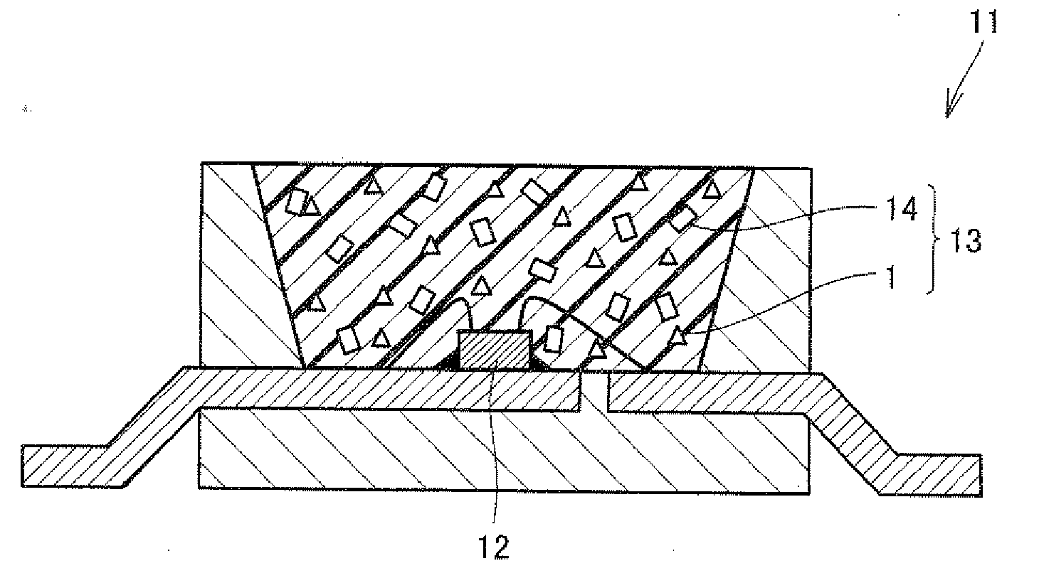
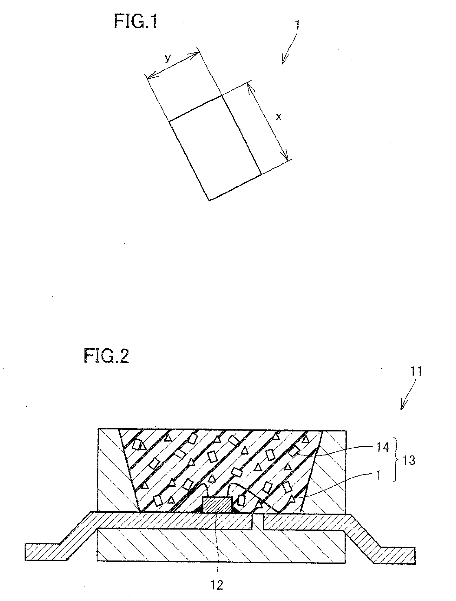
[0042]A gallium nitride (GaN)-based semiconductor having a peak wavelength of 450 nm was used as a light emitting element. A light converter was produced by using a phosphor particle group, which was a particle group of green light emitting phosphor particles having a composition of Eu0.05Si11.50Al0.50O0.05N15.95 (β-type SiAlON) (D50: 7.8 μm), and 85% of which was composed of particles with the value obtained by dividing the longer particle diameter by the shorter particle diameter being greater than 1.0 and not greater than 3.0. The phosphor particle group was prepared by optimizing the oxygen concentration. Here, LA-920 (manufactured by HORIBA. Ltd.) was used as a particle size distribution measuring equipment. The light converter was fabricated by dispersing the phosphor particle group in a prescribed proportion in a sealing material made of thermosetting silicone resin as a medium and then sealing in a light emitting element. A light emitting apparatus of Ex...

examples 2-7

Comparative Examples 2-7

[0045]Light emitting apparatus of Examples 2-7, Comparative Examples 2-7 were produced in the manner similar to Example 1 except the proportion (%) of particles with the value obtained by dividing the longer particle diameter by the shorter particle diameter being greater than 1.0 and not greater than 3.0, and D50, and the light emitting elements, as shown in Table 2. The results of the characteristic (brightness) measured in the manner similar to Example 1 are also shown in Table 2. Table 2 shows that the light emitting apparatus of Examples 2-7 are superior in characteristic (brightness) to the light emitting apparatus of Comparative Examples 2-7.

TABLE 2proportion ofphosphor particles having the valueobtained by dividingthe longer particlepeakdiameter by the shorterwavelengthparticle diameter ofmedianof lightbrightnessgreater than 1.0 andvalueemitting(relativenot greater than 3.0(D50)elementvalue)Example 280% 8.6 μm440 nm104.5%Comparative50% 8.3 μm440 nm100...

example 8

Comparative Example 8

[0046]A gallium nitride (GaN)-based semiconductor having a peak wavelength of 460 nm was used as a light emitting element. A light converter was produced by using: a phosphor particle group, which was a particle group of green light emitting phosphor particles having a composition of Eu0.01Si11.80Al0.20O0.04N15.96 (β-type SiAlON) (D50: 10.5 μm) and, 85% of which was composed of phosphors with the value obtained by dividing the longer particle diameter by the shorter particle diameter being greater than 1.0 and not greater than 3.0; and a divalent europium-activated nitride red light emitting phosphor having a composition of (Ca0.99Eu0.01)AlSiN3 (D50: 9.3 μm). The above-noted phosphor particle group was prepared by optimizing the temperature profile at a time of synthesis. Here, LA-920 (manufactured by HORIBA Ltd.) was used as a particle size distribution measuring equipment. The light converter was fabricated by dispersing the phosphor particle group and the red...


PUM

PropertyMeasurementUnit
Fractionaaaaaaaaaa
Diameteraaaaaaaaaa
Nanoscale particle sizeaaaaaaaaaa

Abstract

Provided is a phosphor particle group of divalent europium-activated oxynitride green light emitting phosphor particles each of which is a β-type SiAlON substantially represented by a general formula: EuaSibAlcOdNe, where 0.0055≦a≦0.4, b+c=12, d+e=16, wherein 60% or more of the phosphor particle group is composed of the phosphor particles in which a value obtained by dividing a longer particle diameter by a shorter particle diameter is greater than 1.0 and not greater than 3.0. A high-efficiency and stable light emitting apparatus using a β-type SiAlON, which includes a light converter using the phosphor particle group, and a phosphor particle group therefor are also provided.

Description

TECHNICAL FIELD[0001]The present invention relates to a particle group of phosphor particles (phosphor particle group) suitable for light emitting apparatus and a light emitting apparatus using the same in a light converter.BACKGROUND ART[0002]Light emitting apparatus using a combination of light emitting elements and phosphors attracts attention as a next generation light emitting apparatus expected to realize low power consumption, compact size, high intensity, high color gamut, and high color rendition, and are actively researched and developed. Primary light emitted from a light emitting element in a range from the longer ultraviolet to the visible blue, i.e. 380-480 nm, is usually used. Light converter using various phosphors suitable for this application are also proposed.[0003]At present, as a white light emitting apparatus of this type, a combination of a light emitting element emitting blue light (peak wavelength: around 460 nm) and a trivalent cerium-activated (Y, Gd)3(Al,...

Claims


Application Information

Patent Timeline
IPC IPC(8): H01J1/63C09K11/79H01L33/50
CPCC01B21/0826C01P2004/54C01P2004/61C01P2006/60C04B35/597C04B2235/3224Y10T428/2982C04B2235/5436C04B2235/767C04B2235/9646C09K11/0883C09K11/7734H01L33/502C04B2235/5296H01L2924/181H01L2224/48091H01L2224/48247H01L2224/48257H01L2224/73265C09K11/77348H01L2924/00014H01L2924/00012
Inventor HANAMOTO, TETSUYAMASUDA, MASATSUGUTERASHIMA, KENJI
Owner DENKA CO LTD
Learn More