

Exhaust gas recirculation device of internal combustion engine, and control method for the device
- Summary
- Abstract
- Description
- Claims
- Application Information
AI Technical Summary
Benefits of technology
Problems solved by technology
Method used
Image

Examples
first embodiment
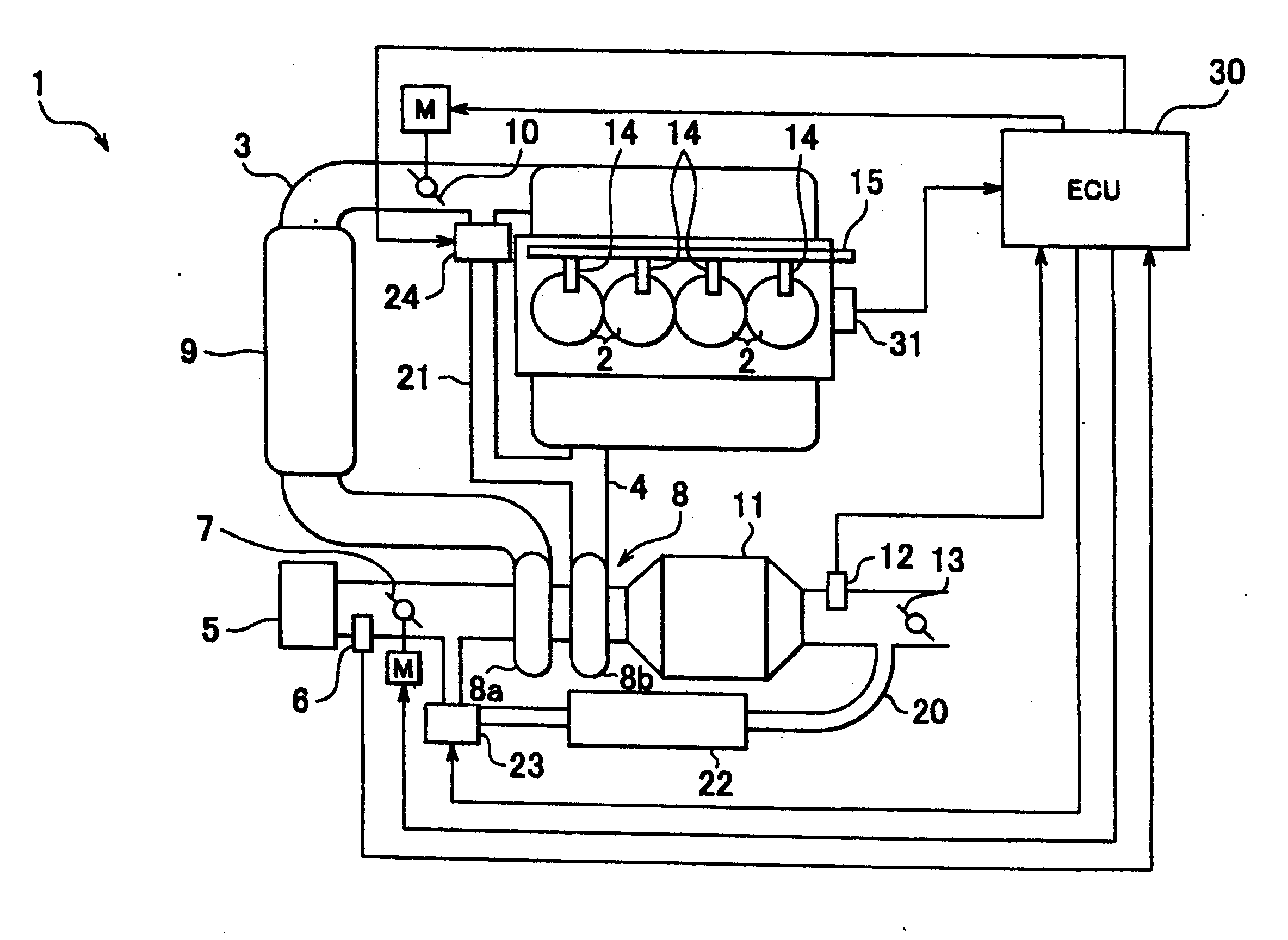
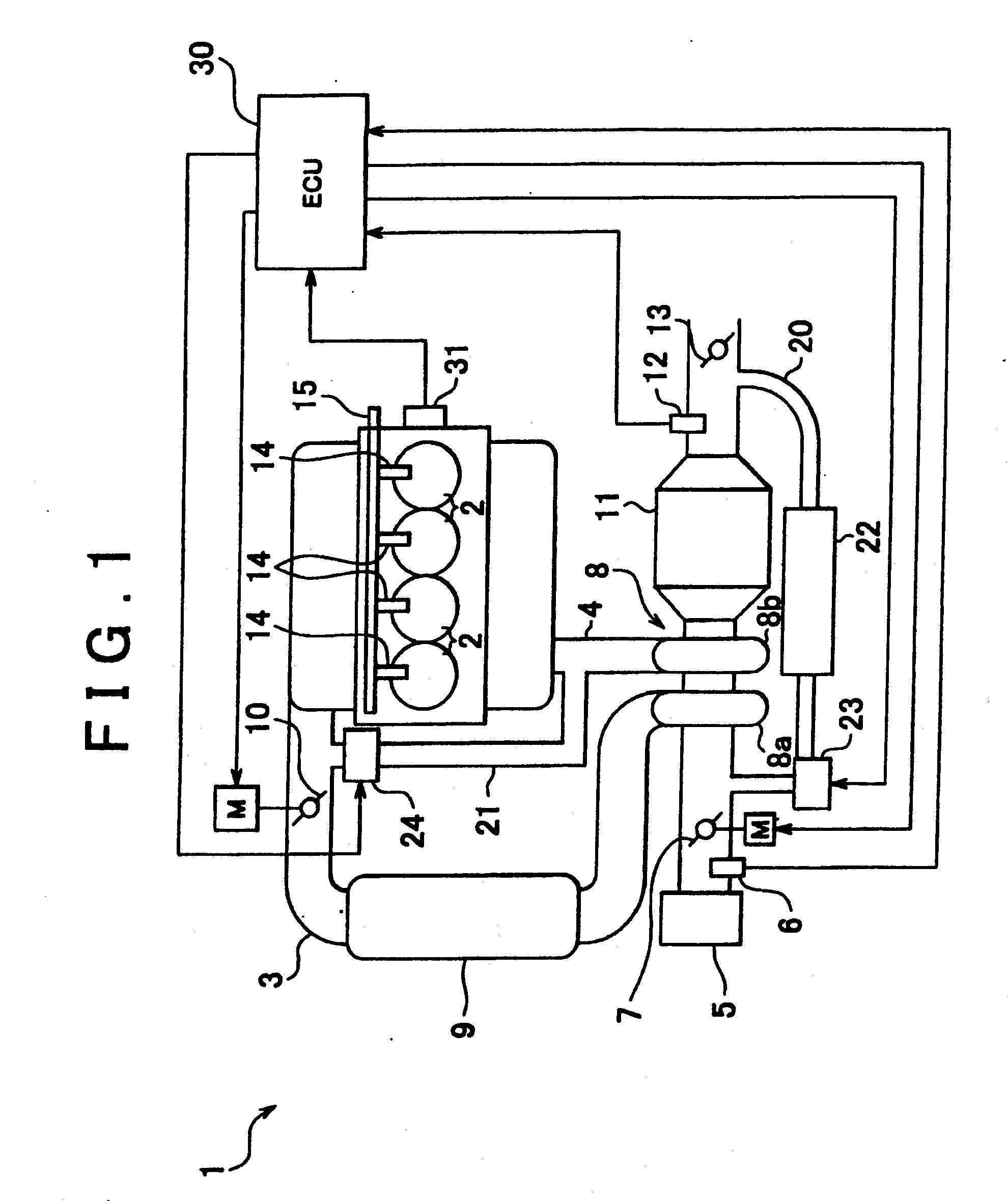
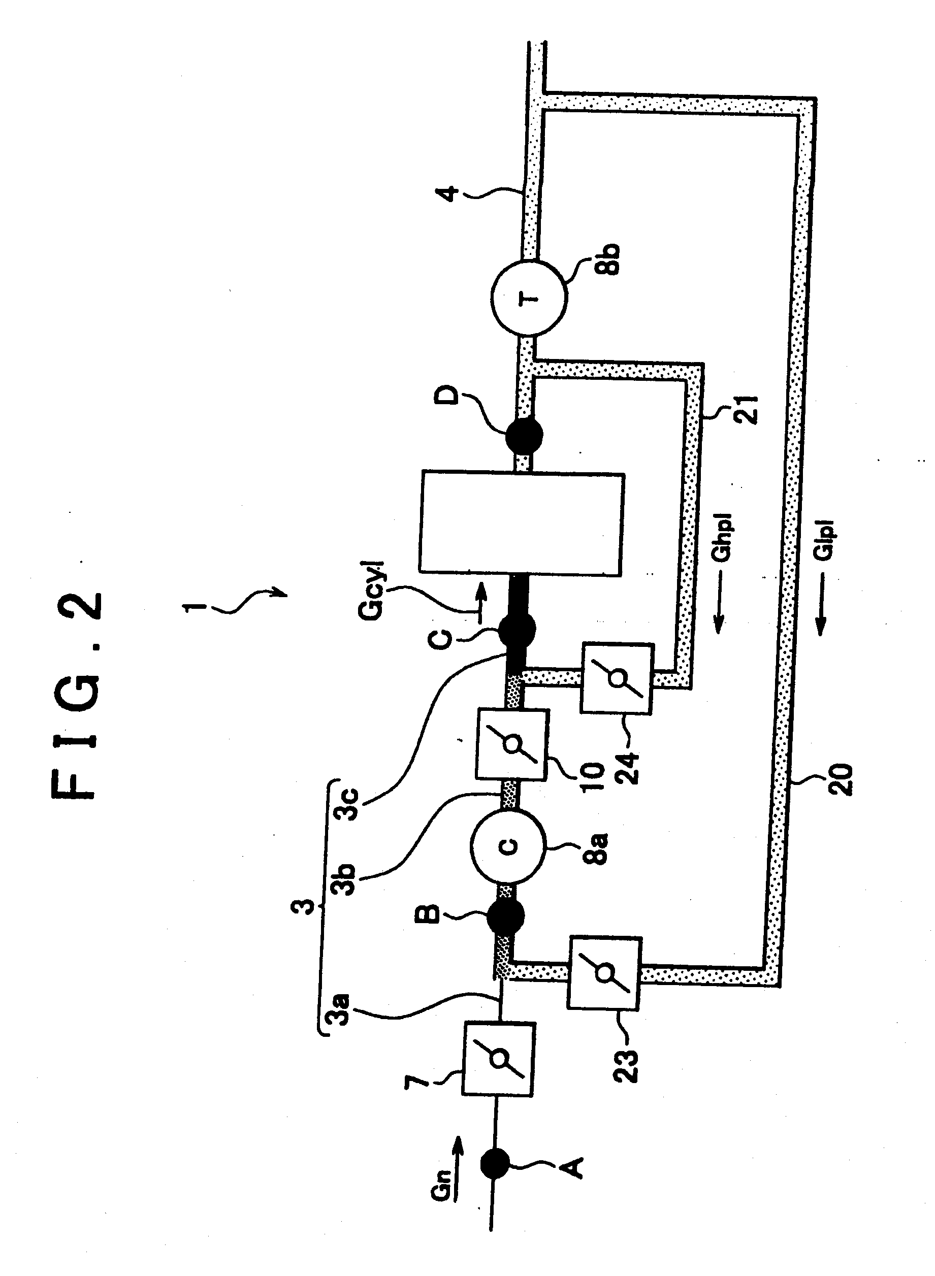
[0033]FIG. 1 shows an example of an internal combustion engine in which an exhaust gas recirculation device in accordance with a first embodiment of the invention is incorporated. The internal combustion engine (hereinafter, sometimes referred to as the engine) 1 shown in FIG. 1 is a diesel engine that is mounted in a vehicle as a traveling motive power source, and has a plurality of cylinders 2 (four cylinders in FIG. 1), and an intake passage 3 and an exhaust passage 4 that are connected to the cylinders 2. The intake passage 3 is provided with an air filter 5 for filtering intake air, an air flow meter 6 that outputs a signal corresponding to the amount of intake air, a first throttle valve 7 for adjusting the intake air amount, a compressor 8a of a turbocharger 8, an intercooler 9 for cooling intake gas, and a second throttle valve 10 for adjusting the intake gas amount. The exhaust passage 4 is provided with a turbine 8b of the turbocharger 8, an exhaust purification catalyst 1...
second embodiment
[0058]Next, a second embodiment of the invention will be described with reference to FIGS. 6 to 8. As shown in FIG. 6, in the second embodiment, an air-fuel ratio sensor 12 is provided in an exhaust manifold 40 that forms a portion of an exhaust passage 4. That is, in the second embodiment, the air-fuel ratio sensor 12 is provided in the exhaust passage 4 upstream of the position of its connection with a high-pressure EGR passage 21. The second embodiment is different in this respect from the first embodiment, and in the other respects, is substantially the same as the first embodiment. Therefore, the portions common between the first and second embodiments are presented with the same reference characters, and descriptions thereof are omitted below. FIG. 7 shows a portion of an EGR gas amount-estimating routine that an ECU 30 in the second embodiment repeatedly executes at every predetermined cycle period during operation of the engine 1. Incidentally, FIG. 7 corresponds to the port...
third embodiment
[0062]A third embodiment of the invention will be described with reference to FIGS. 9 to 14. FIG. 9 shows an engine in which an exhaust gas recirculation device in accordance with a third embodiment of the invention is incorporated. Incidentally, portions common between FIGS. 9 and 1 are presented with the same reference characters, and descriptions thereof are omitted below. As shown in FIG. 9, the third embodiment is different from the other embodiments, in that an O2 sensor 50 as oxygen concentration acquisition means for outputting a signal corresponding to the concentration of oxygen, which is a measurement-object gas, is provided in an intake passage 3 downstream of the position of its connection with the high-pressure EGR passage 21. Incidentally, as shown in FIG. 9, the O2 sensor 50 is provided in an intake manifold 51 that forms a portion of an intake passage 3. Besides, the high-pressure EGR passage 21 is provided with an exhaust purification catalyst 52, and the second th...
PUM
 Abstract
Description
Claims
Application Information