

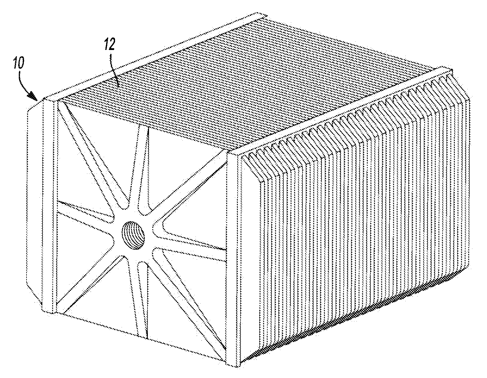
Bipolar battery assembly
a battery assembly and bipolar technology, applied in the field of batteries, can solve the problems of ineffective application use, limited extent to which conventional battery performance can be improved, and battery become extremely heavy
- Summary
- Abstract
- Description
- Claims
- Application Information
AI Technical Summary
Benefits of technology
Problems solved by technology
Method used
Image

Examples
example 1
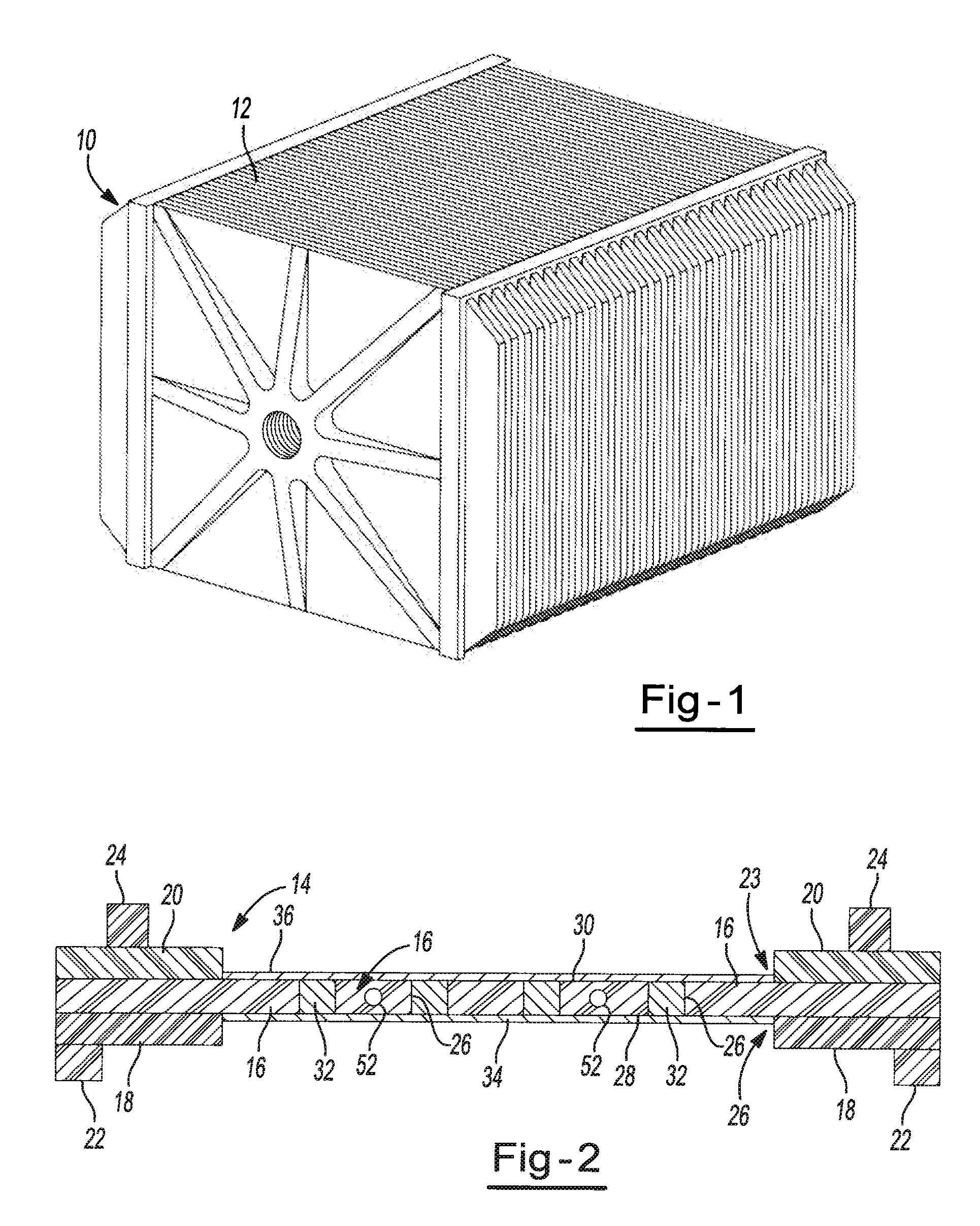
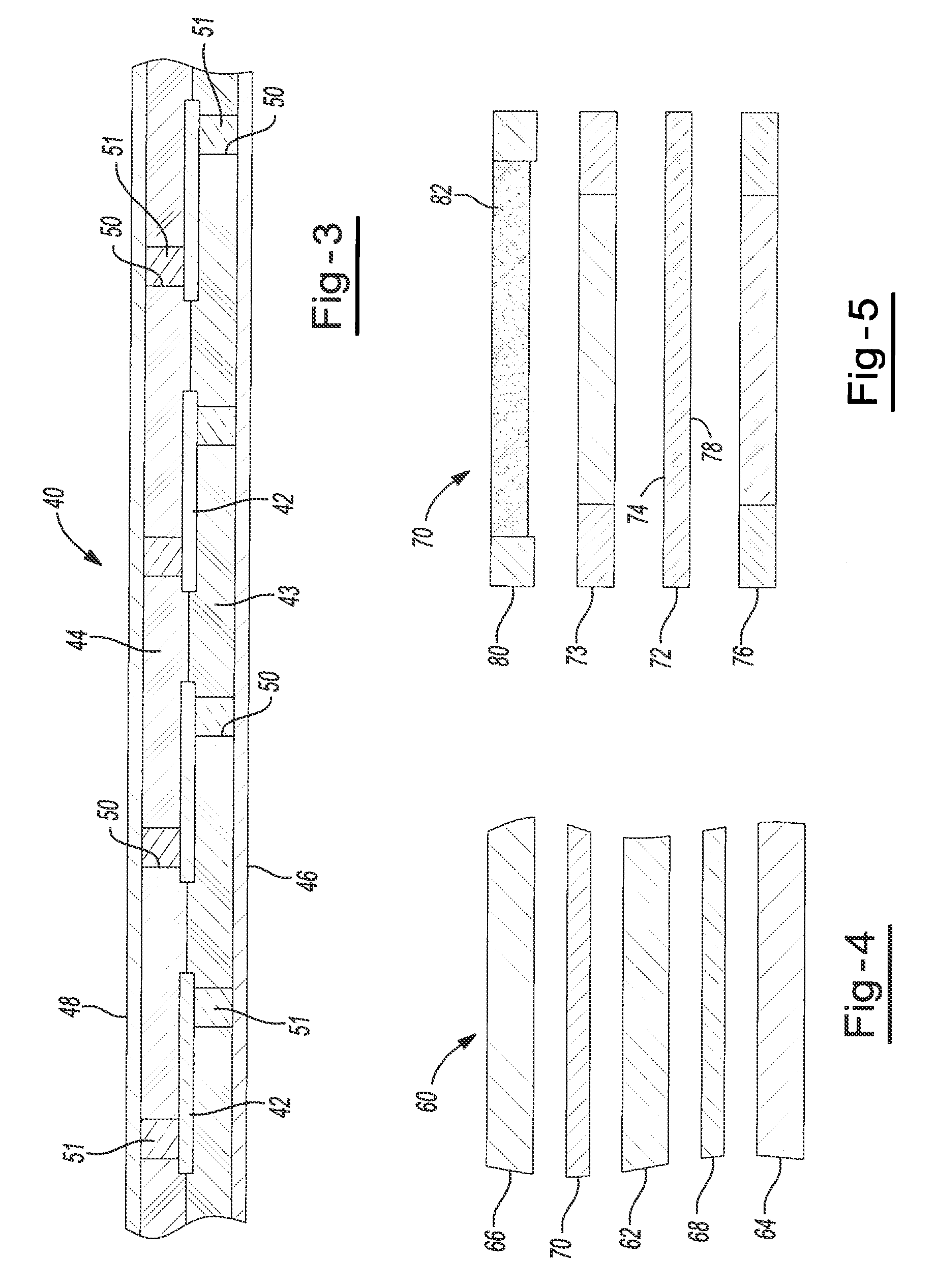
Bipolar Electrode with Epoxy Laminate Substrate
[0099]Epoxy laminate, FR4 Micarta® board (available from Norplex Micarta, Postville, Iowa) is used as the substrate material. The substrate is 0.8 mm thick and cut to 197×166 mm. Seven hundred and twenty (720) 1.6 mm diameter holes 6.25 mm on center are milled into the substrate. The samples are lightly sanded on both faces and washed with isopropyl alcohol. A rubber-based, thermoset adhesive is then brushed onto both surfaces of the substrate and allowed to dry until it is tack free. Epoxy-based adhesives may also been used.
[0100]Stencil printing is used to print a tin-lead solder paste into the holes of the substrate. NC650 63 / 37 tin-lead solder (available from FCT Assembly, Greely, Colo.) is used in this example. The solder is stencil printed first onto the positive face of the substrate. After printing, lead foil is applied to the face and rolled smooth. The foil is a 3 mil thick, 98.5% lead 1.5% tin foil. Other solders, including t...
example 2
Bipolar Electrode with ABS Thermo-Plastic Substrate
[0104]Acrylonitrile-butadiene-styrene (ABS) plastic sheet is used as the substrate. The substrate is 1.6 mm thick and cut to 197 mm×186 mm. Seven hundred and twenty (720) 1.6 mm diameter holes are milled into the substrate. The samples are lightly sanded on both faces and washed with isopropyl alcohol. A rubber-based, thermoset adhesive is then brushed onto both surfaces of the substrate and allowed to dry until it is tack free.
[0105]Stencil printing is used to print a tin-lead solder paste into the holes of the substrate. NC650 63 / 37 tin-lead solder (available from FCT Assembly, Greely, Colo.) is used in this example. The solder is stencil printed first onto the positive face of the substrate. After printing, lead foil is applied to the face and rolled smooth. The foil is 3 mil thick, 98.5% lead 1.5% tin foil. The substrate is then flipped and solder is stencil printed onto the negative face of the substrate. After printing, lead f...
example 3
Effect of Temperature on Resistance of Electrode
[0110]The effect of temperature on the resistance of bipolar electrodes made in Example 1 without pasting frames attached is studied by varying the amount of time at different temperatures in the press. The samples are diced using scissors into ˜1.25″×1.25″ squares such that each specimen has 9 solder-filled, via holes. In some cases the foil lifted at the edge due to the cutting process. Each sample was rolled again to secure the foil to the substrate.
[0111]The press is heated to the set point temperature and held to ensure that the platens are uniformly heated. Set point temperatures that were tested ranged from: 172° C. (below the eutectic); 182.5° C. (at the eutectic) to 192.5° C. The temperature was measured using a digital type-K thermal couple with resolution to 0.1° C. When the platens were at the initial temperature the press was opened, the sample placed in the center, the press was closed and the timer started. In all cases,...
PUM
| Property | Measurement | Unit |
|---|---|---|
| diameter | aaaaa | aaaaa |
| diameter | aaaaa | aaaaa |
| diameter | aaaaa | aaaaa |
Abstract
Description
Claims
Application Information