
Improved particle beam generator

a generator and particle technology, applied in the direction of beam deviation/focusing by electric/magnetic means, instruments, mass spectrometers, etc., can solve the problem that the design cannot be optimum for a particular energy, and achieve the effect of reducing or substantially eliminating the buildup of charge on one or more of the electrodes

Inactive Publication Date: 2010-07-29
NFAB LTD
View PDF12 Cites 18 Cited by
  • Summary
  • Abstract
  • Description
  • Claims
  • Application Information

AI Technical Summary

Benefits of technology

[0010]The provision of a multiple electrode extraction means immediately adjacent the particle source allows not only the extraction of particles into and through the aperture of the extraction means for subsequent delivery to the accelerating means of the device, but also permits some focussing effecting to be achieved in the relatively short length of the extraction means and for different beam energies because different potentials may be applied to each of the different electrodes in said extraction means.
[0018]Preferably, in any aspect of the invention, the particles are extracted from a cold field emission source using a nanotip. Such arrangement has been previously described in R. H. Fowler and L. Nordheim, Proc. Roy. Soc., A119 (1928) 173, but in a most preferred arrangement, the nanotip is coated with an insulating composition and a semiconductor composition, both being of the order of nanometers in thickness which serves to increase the output electron current of the nanotip and reduce the energy spread of the particle beam emitted therefrom. Preferably, a voltage is applied across the insulating layer by applying a negative voltage to the metal nanotip whilst connecting the semiconductor to earth.
[0024]In this manner, it is possible to obtain a source which has almost no aberrations and thus preserves the intrinsic field emission properties of the nanotip.
[0025]In a preferred arrangement, the source is a nanotip which is sharpened by focussed ion beam (FIB) milling so as to reduce the area at the tip from which electrons can be emitted.
[0026]The aperture may be tapered or altered in a way so as to produce a lensing effect so as to further restrain expansion of the beam. Conical apertures may be employed to reduce scattering of electrons.
[0033]These features have the advantage that a buildup of charge on one or more of the electrodes may be reduced or substantially eliminated. This in turn has the advantage that a focussing and steering effect of one or more of the electrodes is not compromised substantially by the presence of charge on one or more of the electrodes.

Problems solved by technology

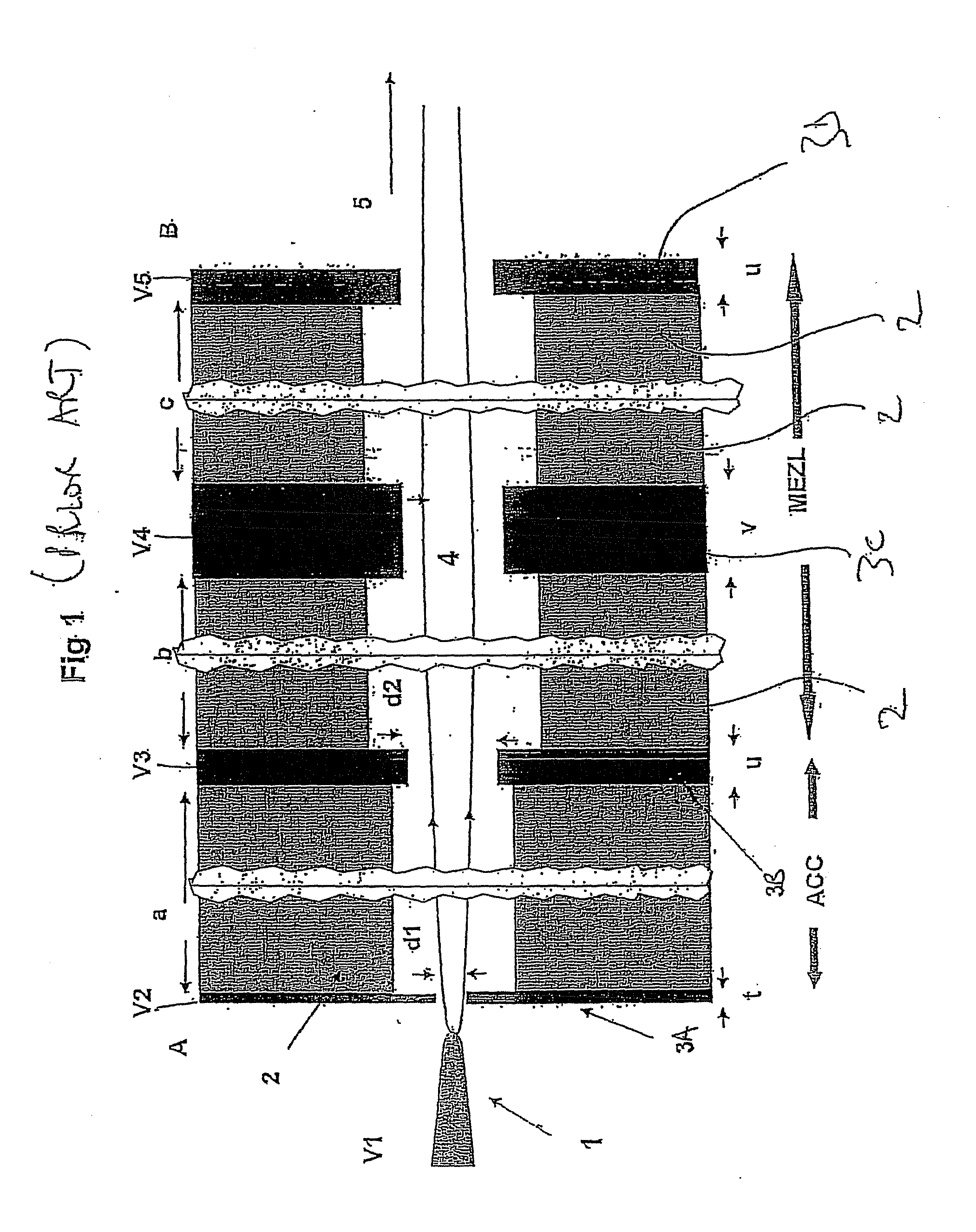
One of the main disadvantages of this arrangement is that the entrance aperture focusing effect depends on the total energy of the electrons, V1, since the strength of the electric field is simply, V2−V3=V1+20 Volts.
This means that one cannot have the same beam divergence or convergence into the microscale einzel lens at all energies and so the design can only be optimum for a particular energy.

Method used


Image

  • Improved particle beam generator
  • Improved particle beam generator
  • Improved particle beam generator

Examples


Embodiment Construction

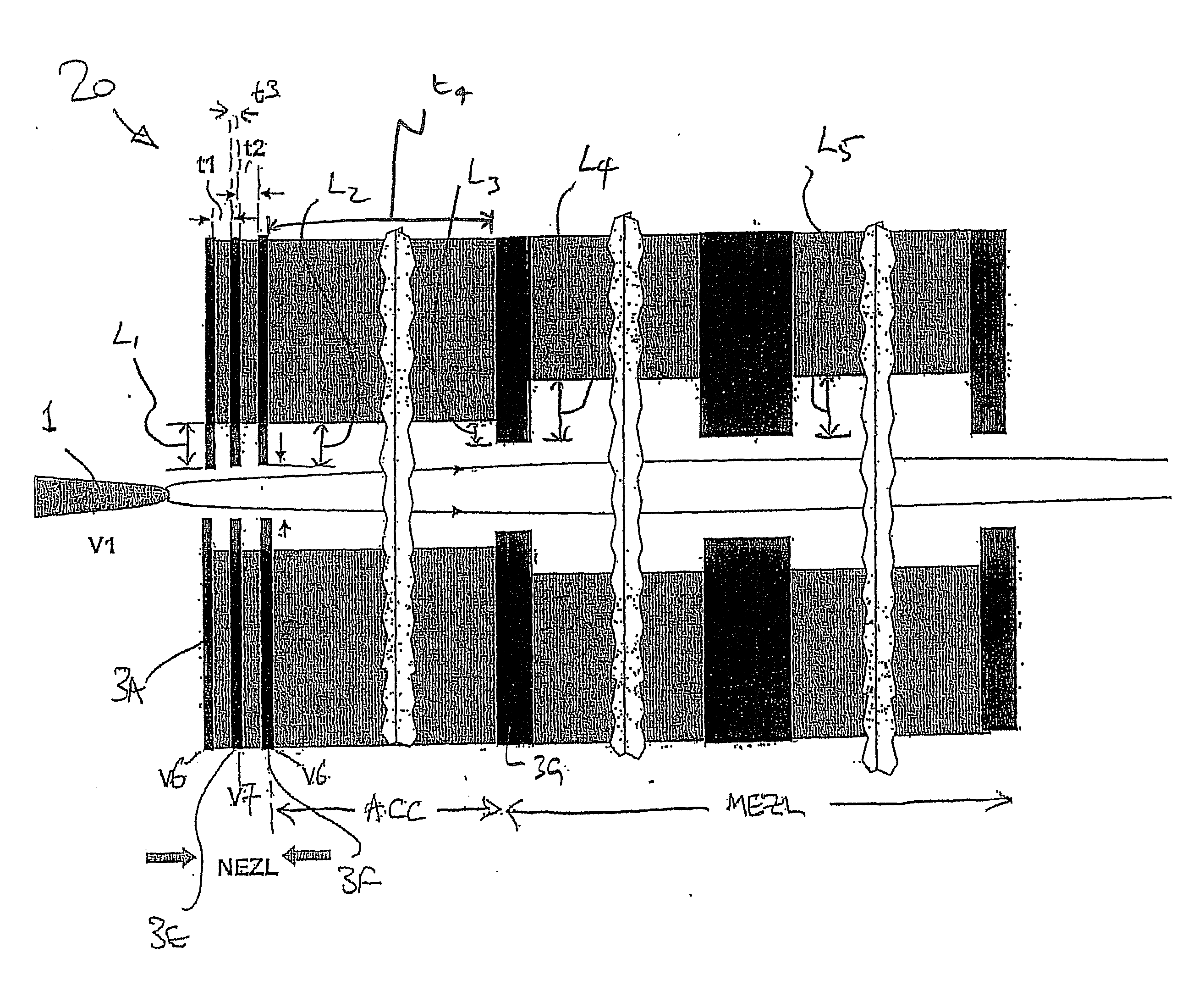
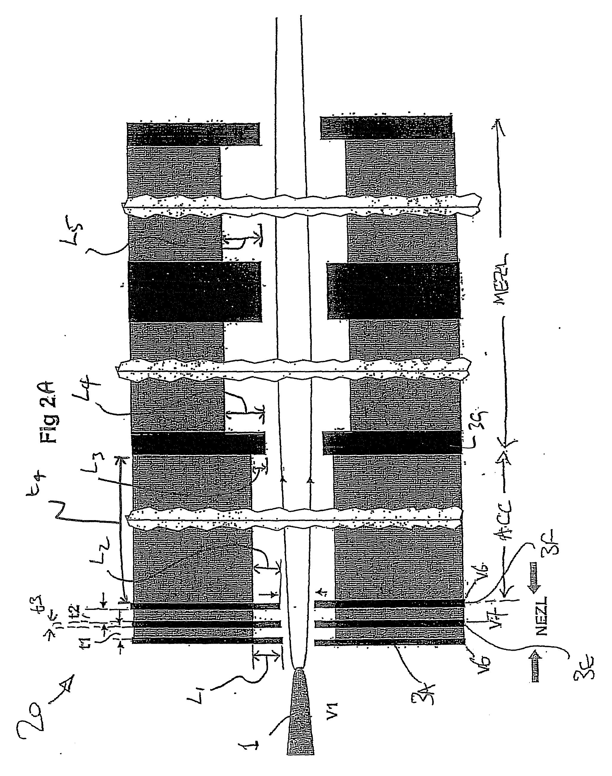
[0059]Referring firstly to FIG. 2, there is shown a particle beam generator 20 comprising a nano-scale Einzel lens structure NEZL, accelerating means ACC and a more standard Einzel lens structure MEZL. The NEZL section is disposed immediately adjacent the particle source or nanotip 1 as shown in FIG. 2. The NEZL section has a total thickness typically less than 200 nm so that the beam does not expand significantly. The aperture in each of the electrodes is typically around 50 nm and the voltage, V7, can be adjusted in the range from −50 to +50 Volts when the thickness of the insulators t1 and t2, is 50 nm for electrodes of similar thickness t3, which is ideally between 10-60 nm. Altering this voltage, V7, changes the beam divergence or convergence into the subsequent accelerator and microscale einzel lens (MEZL) sections of the device and so it is possible to constrain the exiting particle beam to have the same properties irrespective of the overall particle energy. In some embodime...


PUM


Abstract

A particle beam generator comprising particle extraction means disposed adjacent a particle source and operable to extract particles from such a source into an extraction aperture of the extraction means to form a particle beam, particle accelerating means operable to accelerate the extracted particles to increase the energy of the beam, and focussing means operable to focus the particle beam, each of said extraction means, accelerating means and focussing means being arranged in sequence and having apertures therethrough and in alignment to define a passageway through which the particles are constrained to move, characterised in that the extraction means comprises a lens structure comprising at least a pair of electrodes separated by a layer of insulating material allowing the application of different potentials to each of the lens structure electrodes, one of said electrodes comprising an extraction plate having an extraction aperture formed therein, by means of which extraction plate particles may be drawn from the particle source and through the extraction aperture by means of a potential difference between the source and said extraction plate.

Description

[0001]This invention relates to an improved particle beam generator, and more specifically to a sub-miniature scanning electron microscope (SEM).[0002]Although the following description relates in the main to scanning electron microscopes, it is to be mentioned that the application is considered to be of wider scope, and in particular relates to the production of electron and / or ion beams in general.BACKGROUND[0003]In the applicant's earlier International Patent Application WO2003 / 107375 entitled, ‘A Particle Beam Accelerator’, a design for a sub-miniature electron (or ion) beam generator, ideal for a SEM, is described which is capable of focussing electrons (or ions) emanating from a nanotip at low energies (as little as 300 eV) down to atomic dimensions. In the case of a SEM, the substrate onto which the beam is focussed will be the specimen under examination, but other uses for the beam, and the manner in which it reacts with, is reflected by or adsorbed into the specimen are con...

Claims


Application Information

Patent Timeline
IPC IPC(8): H01J37/10H01J3/14
CPCB82Y15/00H01J37/065H01J37/073H01J37/12H01J37/28H01J2237/1207H01J2237/0492H01J2237/062H01J2237/06341H01J2237/1205H01J2237/03
Inventor EASTHAM, DEREK ANTHONY
Owner NFAB LTD
Learn More