
Apparatus and method for testing semiconductor and semiconductor device to be tested

a technology for semiconductor devices and apparatus, applied in individual semiconductor device testing, semiconductor/solid-state device testing/measurement, instruments, etc., can solve the problems of increasing cost, inability to ensure sufficient durability, and difficulty in manufacturing, so as to improve productivity, reduce testing time, and improve the number of semiconductor chips simultaneously measured

Inactive Publication Date: 2010-08-05
NEC CORP
View PDF5 Cites 15 Cited by
  • Summary
  • Abstract
  • Description
  • Claims
  • Application Information

AI Technical Summary

Benefits of technology

[0029]Next, problems of the noncontact scheme will be described. The inventions disclosed in both Patent Document 5 and Patent Document 6 are of a noncontact-type, and therefore have an advantage in which contact traces on the semiconductor device electrode can be eliminated, but there is a problem with a power supply. Wirelessly supplying power is extremely inefficient in terms of transmission efficiency, transmission of desired power requires formation of a large coil, and an area needs to be secured inside the chip, which increases the chip size and increases cost.
[0031]Here, the LSI apparatus for conducting a test and the probe pin of the power supply unit need to be designed so as not to interfere with each other, a region needs to be secured inside the chip and further improvements are expected in terms of the chip size and cost. Furthermore, though the power supply unit and the LSI apparatus for conducting a test are provided with a silicon through-hole electrode and thereby mounted on an intermediate board, there is a problem in which the silicon through-hole electrode requires high cost, yet results in low yield.
[0033]It is an object of the present invention to provide a semiconductor testing apparatus and a testing method capable of improving the number of semiconductor chips simultaneously measured in a wafer testing step or realizing wafer batch test, and thereby reducing the testing time and improving productivity.

Problems solved by technology

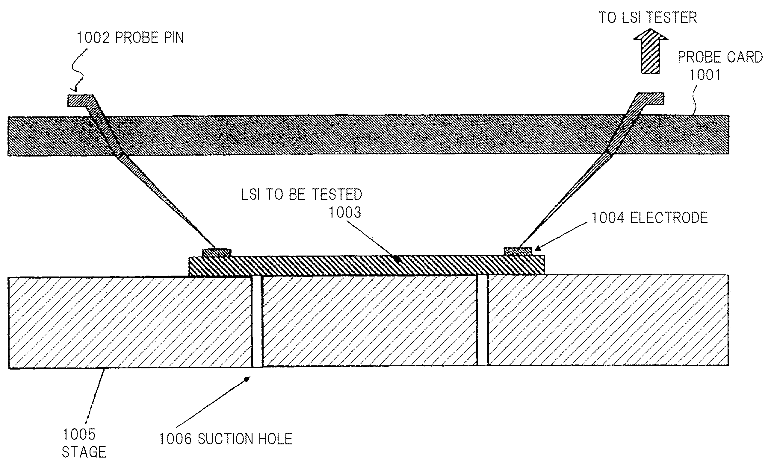
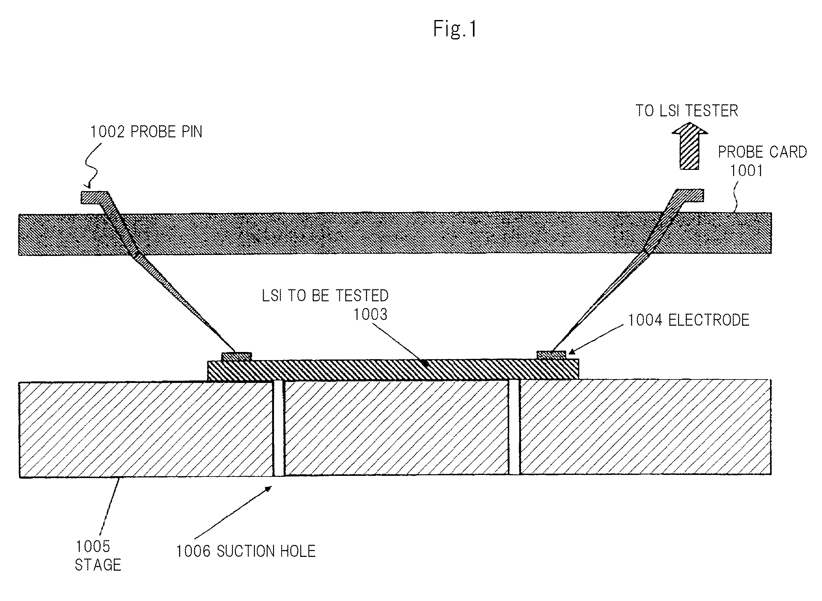
However, the semiconductor testing apparatus adopting a metal needle or projection contact scheme represented by Patent Document 1 has several problems.
First, a probe is configured by laminating four stages of the metal needle and shielding plate from the standpoint of pitch reduction and high-speed signal transmission, and achieving further pitch reduction requires fine machining of the metal needle and a change of material, which makes it very difficult to perform manufacturing and which increases cost.
Furthermore, although the metal needle can be machined, sufficient durability cannot be secured due to insufficient rigidity of the metal needle.
Furthermore, since the needle is long, there is a problem in which transmission loss of signals due to resistance increases, thereby producing large signal delays and making it difficult to support high frequencies.
However, this is a structure that makes contact with an external electrode of the semiconductor device that uses a metal projection (bump), the metal projection needs to be kept to a certain height or more so as not to contact the circuit surface of the semiconductor device at the time of contacting, and since a manufacturing method using plating is used, it is difficult to make the metal projection adaptable to pitch reduction.

Method used


Image

  • Apparatus and method for testing semiconductor and semiconductor device to be tested
  • Apparatus and method for testing semiconductor and semiconductor device to be tested
  • Apparatus and method for testing semiconductor and semiconductor device to be tested

Examples


Embodiment Construction

[0068]Next, exemplary embodiments of the present invention will be described in detail with reference to the accompanying drawings.

[0069]In the exemplary embodiments described below, power is supplied to each chip in a wafer using dedicated wiring used only for a power supply at the time of a test. This dedicated wiring is arranged within the wafer in a well-balanced manner to prevent any voltage drop or the like from occurring, and input from outside is connected to a dedicated wiring for a power supply. When the test is completed and the chip is divided into individual pieces, this dedicated wiring for a power supply is cut through dicing. The chip divided into individual pieces is packaged and operated using connections of another power supply wiring provided in the chip beforehand and used at the time of division into individual pieces or wire bonding or the like.

[0070]FIG. 3 is a cross-sectional view illustrating a configuration of a first exemplary embodiment of a semiconducto...


PUM


Abstract

Provided is a semiconductor testing apparatus which can perform batch test of semiconductor wafers. In the semiconductor testing apparatus, an LSI apparatus for conducting a test and which provided with a circuit and an electrode for transmitting noncontact signals, and a probe card to which a contact-type probe pin is attached are separately arranged. The semiconductor testing apparatus is provided with a recognition unit for precisely aligning the electrodes of the LSI apparatus for conducting a test, the LSI wafer to be tested and the probe card. The LSI apparatus for conducting a test and a probe pin of the probe card are mounted on a stage or a pressurizing head, and contact can be made to sandwich an LSI wafer to be tested, from both the front surface and the rear surface of the LSI wafer to be tested at the same time.

Description

TECHNICAL FIELD[0001]The present invention relates to an apparatus and method for testing semiconductor, and more particularly, to an apparatus and method for testing semiconductor which can reduce the number of pins of a contact probe and perform batch test of wafers, and a semiconductor device to be tested.BACKGROUND ART[0002]In recent years, there is a rapidly growing demand for higher density semiconductor apparatuses, and high-speed and large volume transmission. Increases in the number of electrode terminals are particularly outstanding and pitch reduction is rapidly advancing for both electrodes arranged in and around an area.[0003]In the above described situation, techniques of testing semiconductor devices having fine pitch electrodes are becoming one key technology. In semiconductor device fabrication in particular, how to conduct test of wafers which is an electric test of devices in a wafer state it is a very important issue. It is possible to improve quality through rap...

Claims


Application Information

Patent Timeline
IPC IPC(8): G01R31/26
CPCG01R31/2889G01R31/3025H01L21/6836H01L22/32H01L2924/3011H01L2924/1461H01L2224/16H01L2924/00H01L2224/05548H01L2224/05573H01L2224/05624H01L2924/00014H01L2224/0554H01L2224/05599H01L2224/0555H01L2224/0556
Inventor TAGO, MASAMOTONAKAGAWA, YOSHIHIRO
Owner NEC CORP
Learn More