Large Mode Area Optical Fiber

a technology of optical fiber and large-area optical fiber, applied in the field of optical fiber, can solve the problems of limited beam quality and achieve the effects of suppressing nonlinear effects, high optical power, and limited beam quality

Active Publication Date: 2010-08-05
CORNING INC
View PDF13 Cites 34 Cited by
  • Summary
  • Abstract
  • Description
  • Claims
  • Application Information

AI Technical Summary

Benefits of technology

[0009]The present invention is directed to a large-mode-area (LMA) optical fiber capable of suppressing nonlinear effects while carrying high optical power in a single mode, thus making it particularly suitable for use in connection with high-power fiber lasers and amplifiers. The optical fiber supports single-mode operation at a given wavelength due to the attenuation of higher-order modes, which ensures substantially diffraction limited beam quality. The high attenuation of higher order modes is caused by adding at least one “ring” having a raised refractive index in the inner cladding region. The LMA optical fiber does not require tight bending to become single mode. In some embodiments, the bend diameter is greater than 90 mm. In certain embodiments, the LMA optical fiber requires no bending. The optical fiber effective mode field diameter is scalable up to 40˜50 um, which is about twice of that of existing optical fibers. As a result, a fiber laser system that uses the LMA optical fiber of the present invention can support up to about 10 times more power than a conventional LMA fiber without the onset of above-mentioned detrimental nonlinear effects.

Problems solved by technology

The optical fiber supports single-mode operation at a given wavelength due to the attenuation of higher-order modes, which ensures substantially diffraction limited beam quality.

Method used


Image

  • Large Mode Area Optical Fiber
  • Large Mode Area Optical Fiber
  • Large Mode Area Optical Fiber

Examples


Embodiment Construction

[0039]Reference will now be made in detail to the present preferred embodiments of the invention, examples of which are illustrated in the accompanying drawings. Whenever possible, the same reference numbers and symbols are used throughout the drawings to refer to the same or like parts.

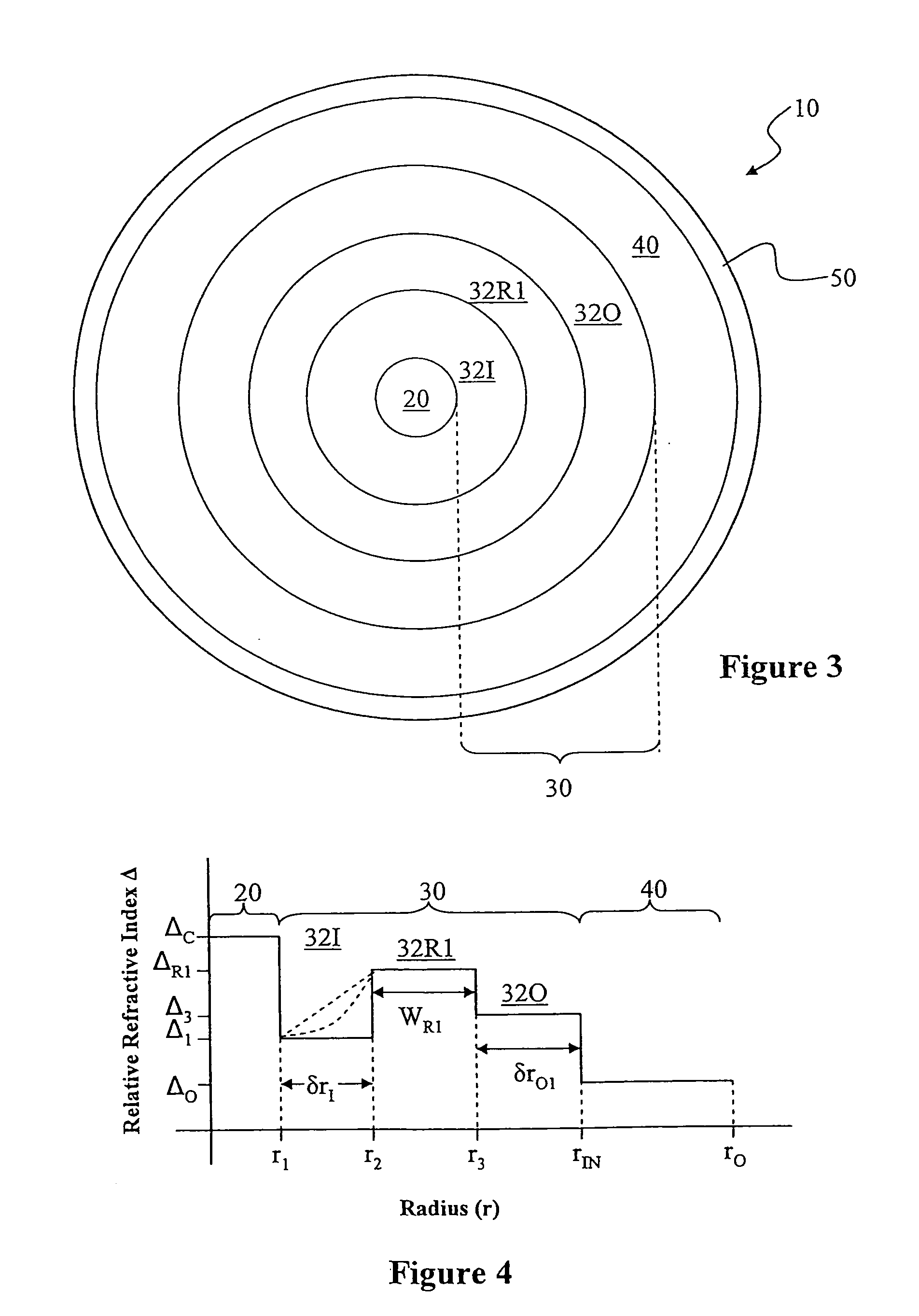
[0040]In the discussion below, the “refractive index profile” is the relationship between refractive index or relative refractive index and waveguide fiber radius. The “relative refractive index percent” for the ith region is defined herein as Δi(%)=[(n12−n12) / 2ni2]×100, where ni is the maximum refractive index in region i, unless otherwise specified, and n1 is the refractive index of the first annular inner section 32I of the inner cladding 32, as discussed below. As used herein, the relative refractive index percent is simply referred to as “the relative refractive index” or “delta” (“Δ”) and its values are given in units of “%”, unless otherwise specified or as is apparent by the context of the di...


PUM


Abstract

A large-mode-area (LMA) optical fiber (10) that operates as a single-mode optical fiber. The optical fiber includes a core region (20) surrounded by an inner cladding (32), which in turn is surrounded by an outer cladding (40). The inner cladding includes at least one up-doped ring region (32R1). The ring region is configured to form a large attenuation differential between the higher-order modes and the fundamental mode so only that the fundamental mode remains traveling in the optical fiber. If necessary, the optical fiber can include a bend (10B) having a select “resonant” bend diameter (DB) that increases the relative attenuation of the fundamental and higher-order modes. The optical fiber supports an effective mode field diameter (MFD) of up to 40 μm to 50 μm. As a result, detrimental non-linear effects are suppressed, which allows the optical fiber to carry substantially more optical power than conventional LMA optical fibers. The LMA optical fiber is thus eminently suited for a number of optical-fiber-based applications calling for high optical power, such as fiber lasers and pump sources for wavelength conversion.

Description

BACKGROUND OF THE INVENTION[0001]1. Field of the Invention[0002]The present invention relates generally to optical fibers, and in particular to an optical fiber having a large mode area and that operate as a single-mode optical fiber due to the attenuation of higher-order modes.[0003]2. Technical Background[0004]Optical fibers are the key component in fiber lasers. High-power, single-frequency fiber lasers have many different applications, including laser radar and imaging, frequency conversion for generating visible or ultra-violet (UV) light, as modules for spectral and coherent beam combining, as biomedical light sources, and in microfabrication.[0005]It is generally desirable for a fiber laser to have as high an output power and as high a brightness as possible. However, as the output power increases, detrimental non-linear effects, such as stimulated Brillouin scattering (SBS) and stimulated Raman scattering (SRS), increase. One way to increase a fiber laser's output power is t...

Claims


Application Information

Patent Timeline
Patent Type & Authority Applications(United States)
IPC IPC(8): H01S3/09G02B6/14G02B6/036H01S3/067B05D5/06
CPCG02B6/024G02B6/03644G02B6/03661G02B6/03688H01S3/094007H01S3/06708H01S3/06712H01S3/06729H01S3/08045G02B6/14
Inventor CHEN, XINKOH, JOOHYUNLI, MING-JUNLIU, ANPING
Owner CORNING INC
Why Eureka
Try Eureka