
Chemical vapor deposition reactor chamber

a chemical vapor deposition and reactor chamber technology, applied in chemical vapor deposition coating, metal material coating process, coating, etc., can solve the problems of large non-uniform boundary layer, large gas rise, and disturbance of laminar flow,

Inactive Publication Date: 2010-08-12
EPIGEE TECH
View PDF24 Cites 36 Cited by
  • Summary
  • Abstract
  • Description
  • Claims
  • Application Information

AI Technical Summary

Benefits of technology

"The present invention provides an improved way of fabricating semiconductor crystals by coating multiple substrates with different reactant gases. The invention includes a reactor chamber with a rotating susceptor, at least two substrates mounted to the susceptor, a heater for heating the susceptor, and two gas injectors that supply reactant gases at an angle to the substrates. The reactor chamber has a peripheral wall with a gas inlet and the susceptor can be moved up and down to change the distance between the heater and the substrates. The invention allows for the formation of a boundary layer caused by heating of the susceptor that is compressed by a pushing gas, resulting in improved quality of the semiconductor crystals."

Problems solved by technology

In addition, heat from the susceptor causes gases to rise and form a large non-uniform boundary layer of hot gas over the substrates and susceptor which can extend to the top surface of the reactor chamber.
These heat convection effects lead to the formation of a boundary layer which results in a recirculating flow pattern and causes a disturbance of the laminar flow.
These disturbances in the laminar flow cause detrimental deposition conditions on the films by changing the uniformity and composition of the deposited thin films across the surface of the substrate.
Another undesirable property of multi-substrate vertical reactors is the adverse effect of deposition of reactants on the surface of the reactant gas injector.
These flow devices often accumulate deposited reactants and disturb the flow pattern over a period of time.
This results in extensive downtime and wasted productivity of the deposition system.
One disadvantage of this system is that a complex susceptor mechanism needs to be employed with mounting face plates, clamps, clips, adhesives, or other mechanisms in order to hold the substrates in place while being held face down.
These mechanisms also disturb the flow pattern of the reactant gases causing non-uniform deposition across the substrate's surface.
Another disadvantage of this reactor is that these mechanisms introduce unwanted impurities onto the substrate's surface during growth.
Another disadvantage of this reactor is the formation of particles on the reactant injector.
This is due to the formation of particles during growth which accumulate on the susceptor and subsequently fall downwards onto the gas injector located on the bottom of the reactor, disturbing the injected flow pattern.
Thus, a cleaning procedure needs to be implemented on a regular basis in order to maintain a predictable flow pattern which results in extensive downtime and wasted productivity of the deposition system.
In addition, heat from the susceptor causes gases to rise and form a large non-uniform boundary layer of hot gas over the substrates and susceptor which can extend to the top surface of the reactor chamber.
These heat convection effects lead to the formation of a boundary layer which results in a recirculating flow pattern causing a disturbance of the laminar flow.
These disturbances in the laminar flow cause detrimental deposition conditions by changing the uniformity and composition of the deposited thin films across the object's surface, similar to the effects observed in vertical reactor designs.
However, these effects are even larger in horizontal reactors for two main reasons.
This leads to an increase in the thickness of the boundary layer.
These two effects greatly diminish the efficiency of the reactants at the substrate.
In addition to the difficulties stated above, current horizontal multi-substrate reactors also suffer from effects caused by parasitic deposition on the reactor walls.
These depositions cause detrimental effects on the deposited films including: changing the flow pattern across the substrate's surface, causing temperature fluctuations over time, and causing particles to drop from the surface onto the substrates.
This results in extensive downtime and wasted productivity of the deposition system.
One disadvantage with the two-flow reactor system as described in the previous paragraphs is that it allows for only one substrate to be deposited at one time.
This single substrate design greatly minimizes the commercial applicability of this deposition technique because of its inherently low throughput.
Another disadvantage of this design is that the supplied reactant gases are directed only on one leading edge of the rotating substrate.
This results in high variability of deposition conditions across the substrate's surface which greatly reduces the uniformity of the deposition across the substrate's surface.
In addition, disruption of the reactant gas flow pattern due to heat convection from the heated substrate and gas flow interactions with the substrate's surface cause perturbations in the laminar flow of the reactant gases across the substrate's surface because the reactants are injected on one leading edge of the susceptor.
Another disadvantage of this design is the added complexity of the use of a forcing gas which has multiple flow patterns and velocities.
The use of multiple flow patterns causes turbulence to develop at the interfaces between these two flows which significantly affect the flow pattern of the reactant gases across the substrate surface.
This results in non-uniform deposition across the substrates and causes inadequate deposition reproducibility.

Method used


Image

  • Chemical vapor deposition reactor chamber
  • Chemical vapor deposition reactor chamber
  • Chemical vapor deposition reactor chamber

Examples


Embodiment Construction

[0041]Referring now to the drawings, in which like numerals refer to like components or steps, there are disclosed broad aspects of various exemplary embodiments.

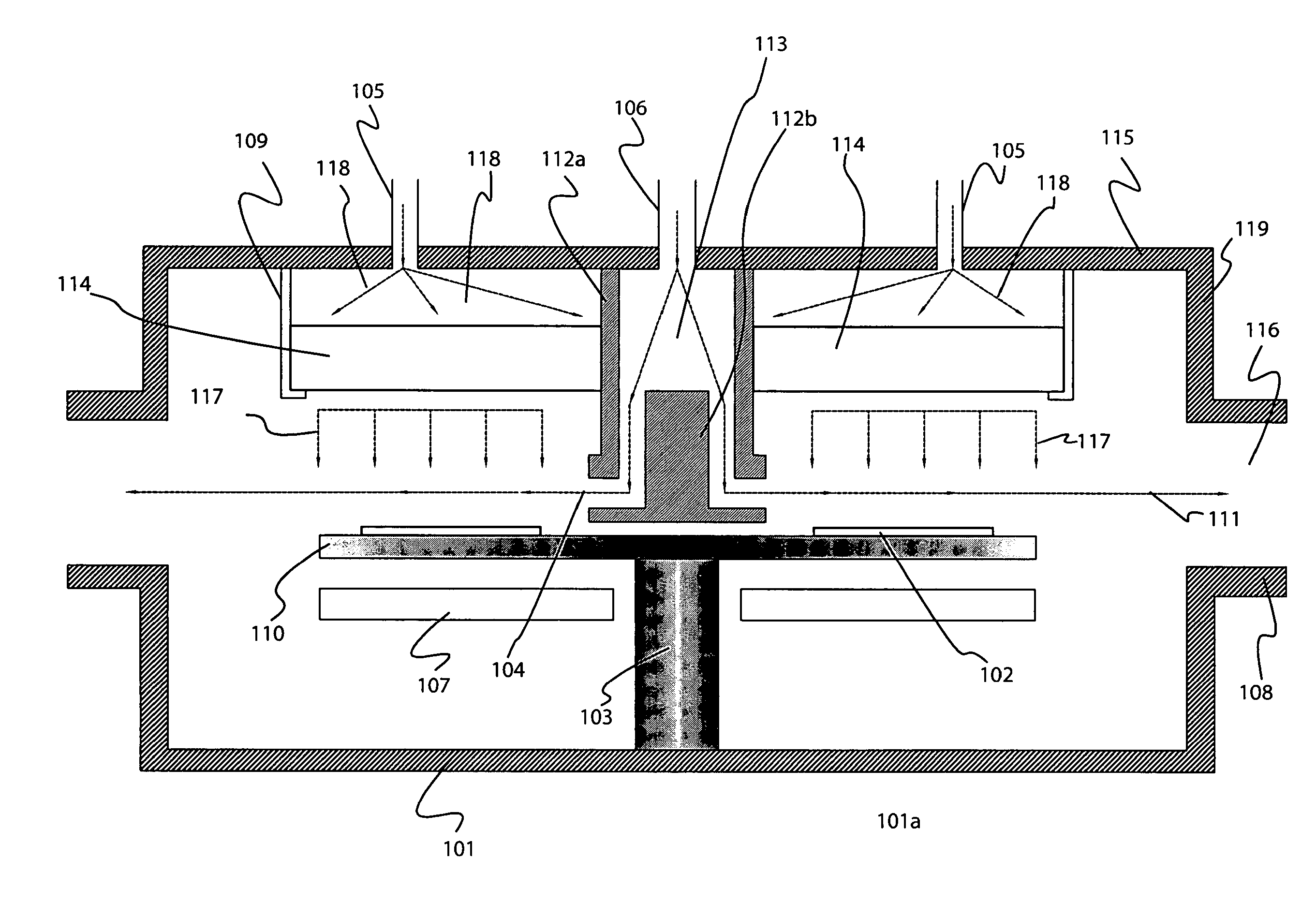
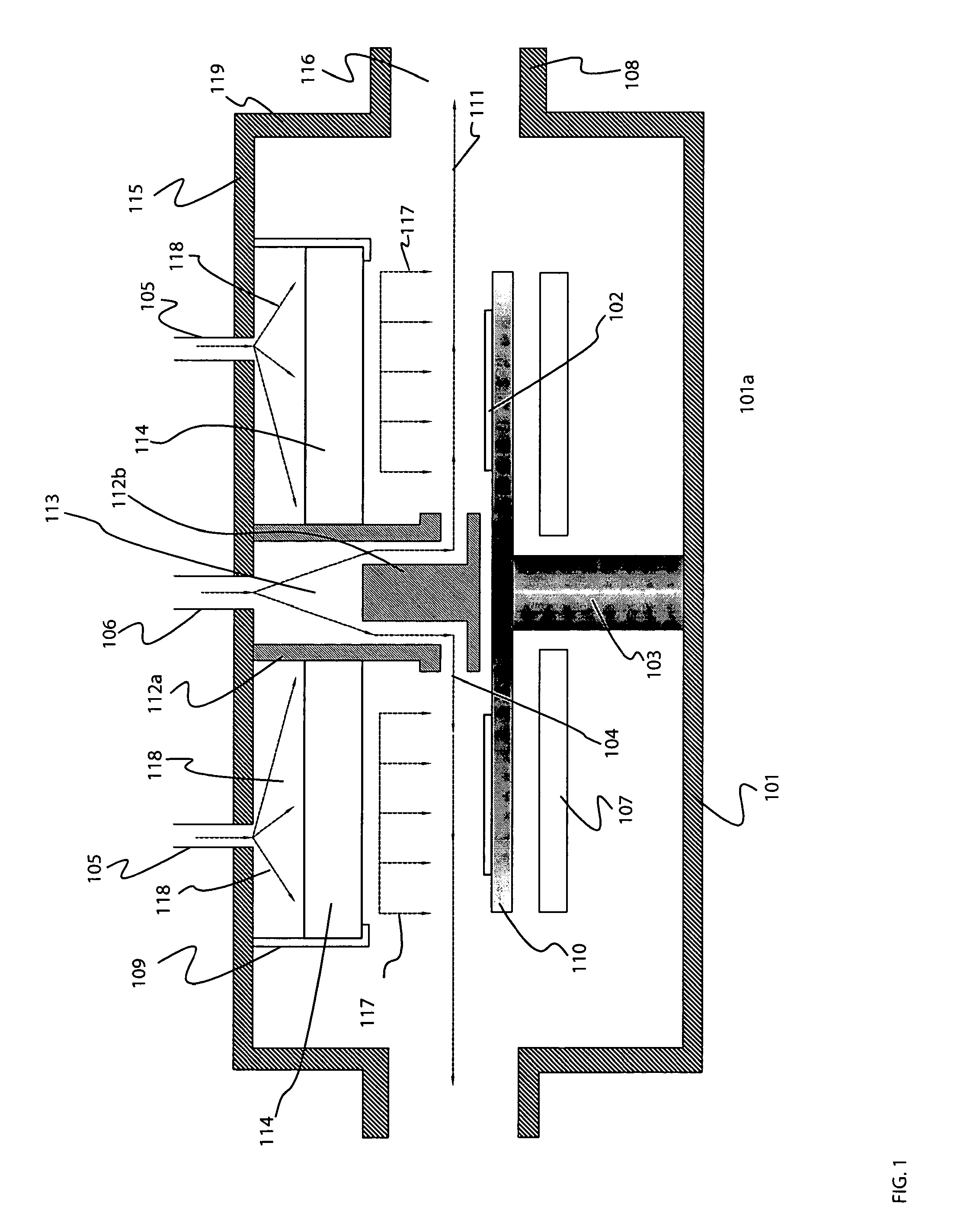
[0042]FIG. 1 is a schematic representation of a vertical sectional view of a multi-wafer dual flow MOCVD reactor 101a showing one embodiment of the principles of this invention.

[0043]The reactor 101a comprises a cylindrical reactor vessel 101 having a reactant gas injector 112a and 112b, a secondary gas injector 114, and a gas exit or exhaust 116. The reactor is roughly cylindrical having a vertical axis. The reactor may have a circular bottom plate with a diameter of about 60 cm, which in turn supports a rotating substrate holder or susceptor 110, on which more than one substrate or other objects are placed. The susceptor has a rotating axis 103 passing through an opening in the bottom plate which is hermetically sealed. Heating means 107 are disposed beneath the susceptor in order to provide heating to the susceptor which...


PUM

PropertyMeasurementUnit
diameteraaaaaaaaaa
distanceaaaaaaaaaa
distanceaaaaaaaaaa

Abstract

A chemical vapor deposition reactor is provided which includes a process chamber accommodating a substrate holder for multiple substrates, and a reactor gas inlet which supplies the reactant gases to a portion above the surface of the heated substrates. The reactant gases can be injected parallel or oblique to the substrates and the angle between the supplied reactant gas flow direction and the tangential component of the susceptor's angular rotation is independent of the susceptor's position. A secondary gas inlet which supplies gases perpendicular or at a sharp angle to the substrates is also included so as to change the boundary layer thickness created when hot gases come into contact with the colder reactant gases flowing parallel or oblique to the surface of the substrates.

Description

[0001]The present invention relates to a metal organic chemical vapor deposition reactor used for the deposition of a semiconductor crystal film on multiple substrates. The invention is particularly related to a chemical vapor delivery apparatus that promotes high reactant efficiency and uniformity.BACKGROUND OF THE INVENTION[0002]Metal Organic Chemical Vapor Deposition (MOCVD) is a standard method for deposition of high quality crystalline thin films used for the fabrication of electronic devices such as light emitting diodes and laser diodes. In general, MOCVD reactors use a metal organic source such as trimethylgallium (TMG) or trimethylindium (TMI) which is then transported by a gas which is inert to the chemical reaction, such as nitrogen or hydrogen, into a chamber. While in the chamber the metal organic compounds are heated, decompose, and then chemically react with a hydride gas, such as ammonia or arsine, to form a thin film on a heated substrate. For example, when TMG and ...

Claims


Application Information

Patent Timeline
Patent Type & Authority Applications(United States)
IPC IPC(8): C23C16/00
CPCC23C16/4584C23C16/45508H01L21/68771
Inventor IZA, MICHAEL
Owner EPIGEE TECH
Learn More