
DC arc plasmatron and method of using the same

a plasmatron and arc technology, applied in plasma techniques, gas-filled discharge tubes, manufacturing tools, etc., can solve the problems of limiting the service life of such a plasmatron, affecting the efficiency of aforementioned techniques, and affecting the service life of water-cooling anodes, so as to prolong the service life and improve the excitation efficiency of process gases, the effect of enhancing the strength and the completion level of chemical reactions

Inactive Publication Date: 2010-08-12
IND ACADEMIC COOPERATION FOUND JEJU NAT UNIVERSTIY
View PDF7 Cites 8 Cited by
  • Summary
  • Abstract
  • Description
  • Claims
  • Application Information

AI Technical Summary

Benefits of technology

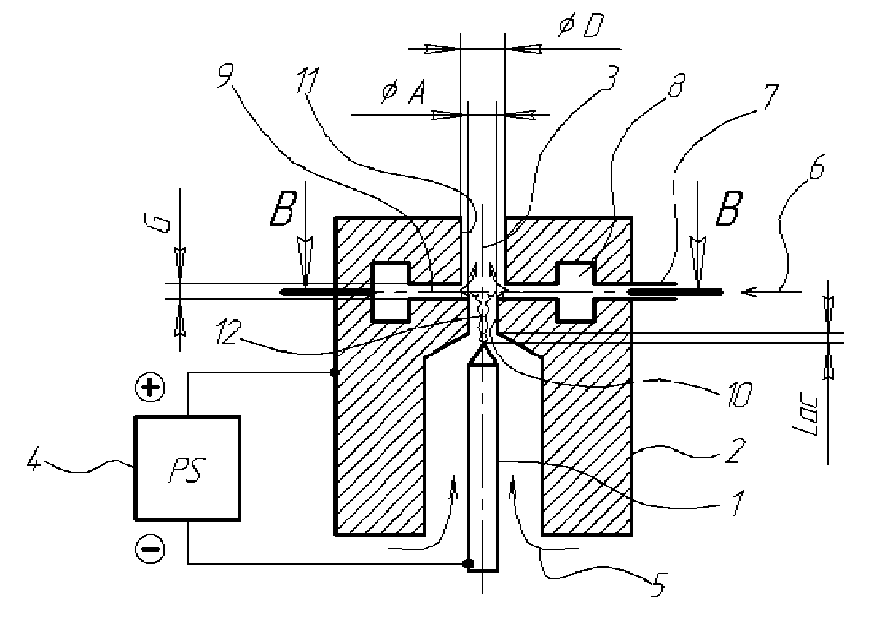
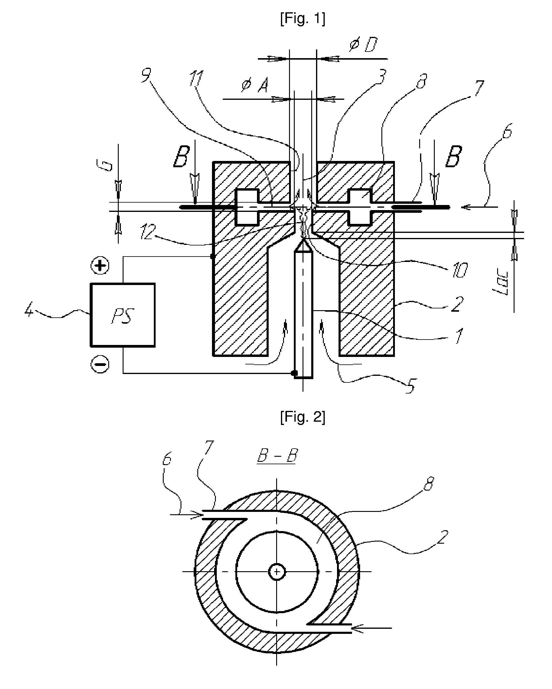
"The invention is a DC arc plasmatron that improves the efficiency of exciting a process gas and enhances the strength and completion level of chemical reactions. It also has a longer service life and improved cleanliness level of created plasma. Additionally, it can control the shape and size of discharged plasma jets for specific purposes."

Problems solved by technology

A water-cooling anode is more severely damaged at a pressure around the atmospheric pressure.
Therefore, it is the anode that limits the service life of such a plasmatron.
The energy efficiency by the aforementioned technique, however, was not so high, due to a low excitation capability of arc plasma.
The reason is presumed to be non-uniform heating of the plasma forming gas in the anode spot area.
In case of using an insertion unit made of refractory metal, the anode spot is also limited to a very small area (the process associated with the anode spot locally existing involves local melting, overheating and implosion).
Accordingly, only a very small part of gas flow contacts the heated anode spot area, and it is thus impossible to reach an average temperature sufficiently high.
Such a phenomenon is an obstacle to completing the chemical process of plasma and lowers a reaction product yield of the plasmatron.
When operation of the plasmatron at a vacuum is intended in order to raise the plasma ionization level and the gas activation level, the aforementioned method cannot be applied.
Arc initiation at a vacuum thus results in dielectric breakdown in the space between electrodes.
In this case, it is impossible to avoid problems by the process that very active arc spots appear both on the anode and the cathode, which contact a dielectric or soldered part that may be easily broken.

Method used


Image

  • DC arc plasmatron and method of using the same
  • DC arc plasmatron and method of using the same
  • DC arc plasmatron and method of using the same

Examples


Embodiment Construction

[0021]The present invention pertains to a DC arc plasmatron.

[0022]The DC arc plasmatron according to the invention comprises a rod cathode 110, a nozzle anode 120 and a gas supply unit.

[0023]More particularly, the invention relates to a DC arc plasmatron comprising a rod cathode connected to a DC power supply, and formed to be positioned close to a nozzle to be a negative, a nozzle anode formed on the nozzle to be a positive, being an opening to inject into a functional gap 150 plasma created by gas discharge for forming the plasma between the cathode and the anode and having an anode inlet 122, a functional gap so that either a function gas or a gas mixture is supplied on some part of the passage around the anode to make it react with the plasma forming gas through the anode inlet 122, and a gas supply unit for supplying a plasma forming gas flowing through the space around the nozzle anode from the side of the rod cathode.

[0024]Now, embodiments of the invention will be described i...


PUM

PropertyMeasurementUnit
temperatureaaaaaaaaaa
sizeaaaaaaaaaa

Abstract

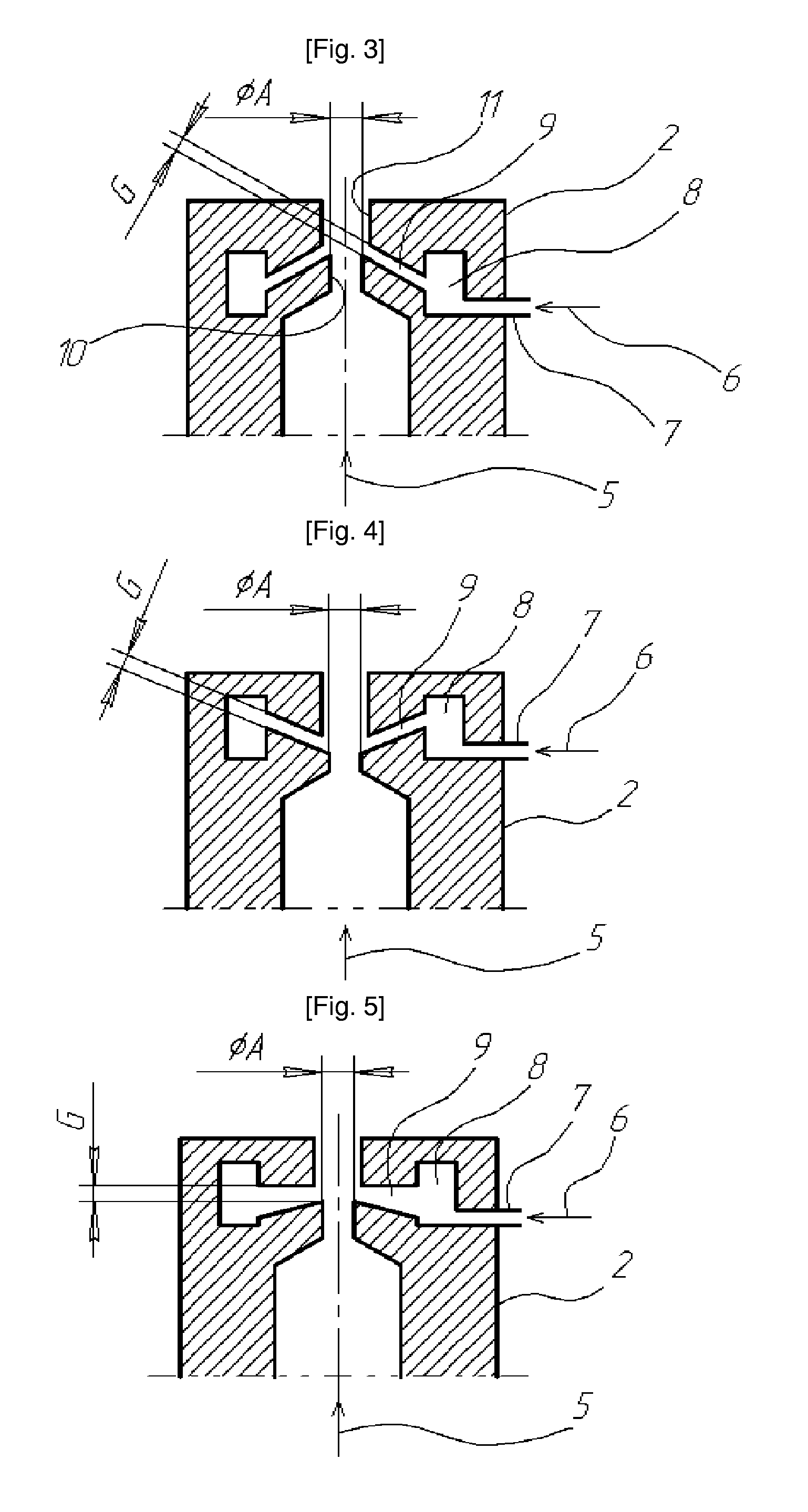
The present invention concerns a DC arc plasmatron which is a plasma generator at the atmospheric pressure having a structure suitable for improving chemical activity of plasma.The DC arc plasmatron according to the invention comprises a rod cathode 110 connected to a DC power supply 1000, and formed to be positioned close to a nozzle to be a negative; a nozzle anode 120 formed on the nozzle to be a positive, being an opening to inject plasma into a functional gap 150 and having an anode inlet 122, wherein the plasma is created by gas discharge for forming the plasma between the cathode and the anode; a functional anode gap formed on the nozzle to be a positive so that either a function gas or a gas mixture is supplied on some part of the passage of the anode to make it react with the plasma forming gas through the nozzle inlet; and a gas supply unit for supplying a plasma forming gas flowing through the nozzle anode from the side of the rod cathode.The anode comprises an anode inlet 122 as an inlet of the functional gap 150; an anode outlet 125 as an outlet of the functional gap 150; the functional gap 150 formed as a disk shaped space 300 communicating with a part of the passage between the anode inlet 122 and the anode outlet 125; a gas collecting chamber 500 formed with a chamber member communicating with the disk shaped space 300; and a functional process gas conduit 600 communicating with the gas collecting chamber 500 and formed so that either the functional gas or a gas mixture can be supplied.The functional gap 150 is formed to have a height G to be 0.3A to 3A with respect to the diameter A of the anode inlet 122. The anode outlet 125 is formed to have a diameter D to be 0.3A to 3A with respect to the diameter A of the anode inlet 122. A method of using the plasmatron according to the invention comprises the steps of: a first step of selecting a proper functional gas, supplying it to the functional process gas conduit 600 and thereafter supplying a plasma forming gas in the space around the rod cathode 110 and the anode 120; a second step of supplying cold water and operating the DC power supply 1000 connected to the plasmatron; a third step of initiating arc discharge by applying high voltage across the rod cathode 110 and the anode 122, and activating the plasma forming gas and the functional gas by interaction therebetween while the plasma forming gas is excited and heated; and a fourth step of, after fixing a process variable to a proper level, discharging the gas in the arc discharge area through the anode outlet 125 of the plasmatron to reach a appropriate vacuum pressure while keeping the process variable at an appropriate level.Chemical activity of plasma jets formed by means of the plasmatron and the method according to the invention is improved and the completion level in the chemical process of plasma by the functional gas is improved.

Description

BACKGROUND OF THE INVENTION[0001]1. Technical Field[0002]The invention relates to a DC arc plasmatron and to a method of using the same.[0003]More particularly, the invention relates to a DC arc plasmatron comprising a rod cathode connected to a DC power supply, and formed to be positioned close to a nozzle to be a negative, a nozzle anode having an anode inlet formed on a nozzle, being an opening to inject plasma created by gas discharge for forming plasma in the space between the cathode and the anode and functioning as an anode inlet, a functional gap formed to be a positive so that either a functional gas or a gas mixture flows in on some part of the passage of the anode to make it react with the plasma forming gas through the anode inlet, and a gas supply unit for supplying the plasma forming gas flowing through the anode inlet from the side of the rod cathode. The inventive DC arc plasmatron is structured to be a shape suitable for improving chemical activity of plasma and is ...

Claims


Application Information

Patent Timeline
Patent Type & Authority Applications(United States)
IPC IPC(8): H05H1/24
CPCH05H1/48H05H1/24H05H1/3468H05H1/3442H05H1/3484H05H1/28H01J37/32055
Inventor LEE, HEON-JUMOK, YONG-SONRIABY, VALENTIN ANATOLIEVICHPLAKSIN, VALDIM YU
Owner IND ACADEMIC COOPERATION FOUND JEJU NAT UNIVERSTIY
Learn More