Quadrature amplitude modulation signal generating device

a signal generator and quadratic amplitude technology, applied in phase-modulated carrier systems, frequency-modulated carrier systems, digital transmission, etc., can solve problems such as difficult to handle multi-level electrical signals

Active Publication Date: 2010-08-12
NAT INST OF INFORMATION & COMM TECH
View PDF34 Cites 38 Cited by
  • Summary
  • Abstract
  • Description
  • Claims
  • Application Information

AI Technical Summary

Benefits of technology

[0043]According to the present invention, a quadrature amplitude modulation signal generator which ca...

Problems solved by technology

However, such technology has a problem that it...

Method used


Image

  • Quadrature amplitude modulation signal generating device
  • Quadrature amplitude modulation signal generating device
  • Quadrature amplitude modulation signal generating device

Examples


first example

16 QAM Mapping Using Two QPMZMs

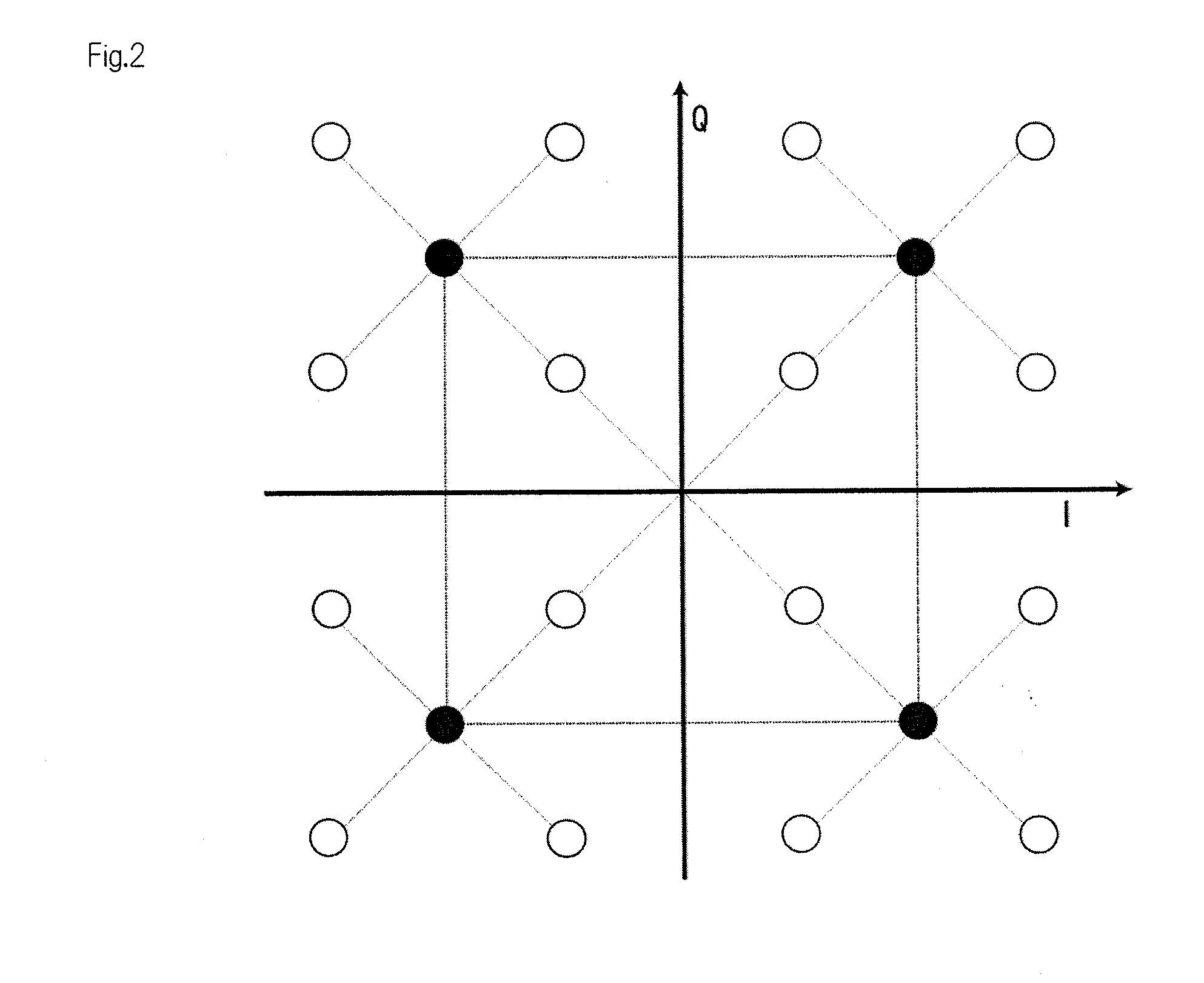
[0093]FIG. 4 shows a diagram illustrating the principle of a 16 QAM modulator of the present invention. In this example, two kinds of QPSK signals having different amplitudes (intensity) are superimposed on each other in order to obtain 16 QAM signals. The intensity difference between the two QPSK signals was set to be 6 dB. The QPSK signal having larger amplitude (which is shown by QPSK2 in FIG. 4) determines the area in which a quadrant is mapped. Meanwhile, the QPSK signal having smaller amplitude (which is shown by QPSK1 in FIG. 4) fixes the position of each quadrant. By combining two QPSK signals with each other, 16 equally-spaced symbols can be mapped in a phase diagram. This 16 QAM mapping can be obtained using binary data without using multilevel electrical signals.

second example

QPMZM for 16 QAM

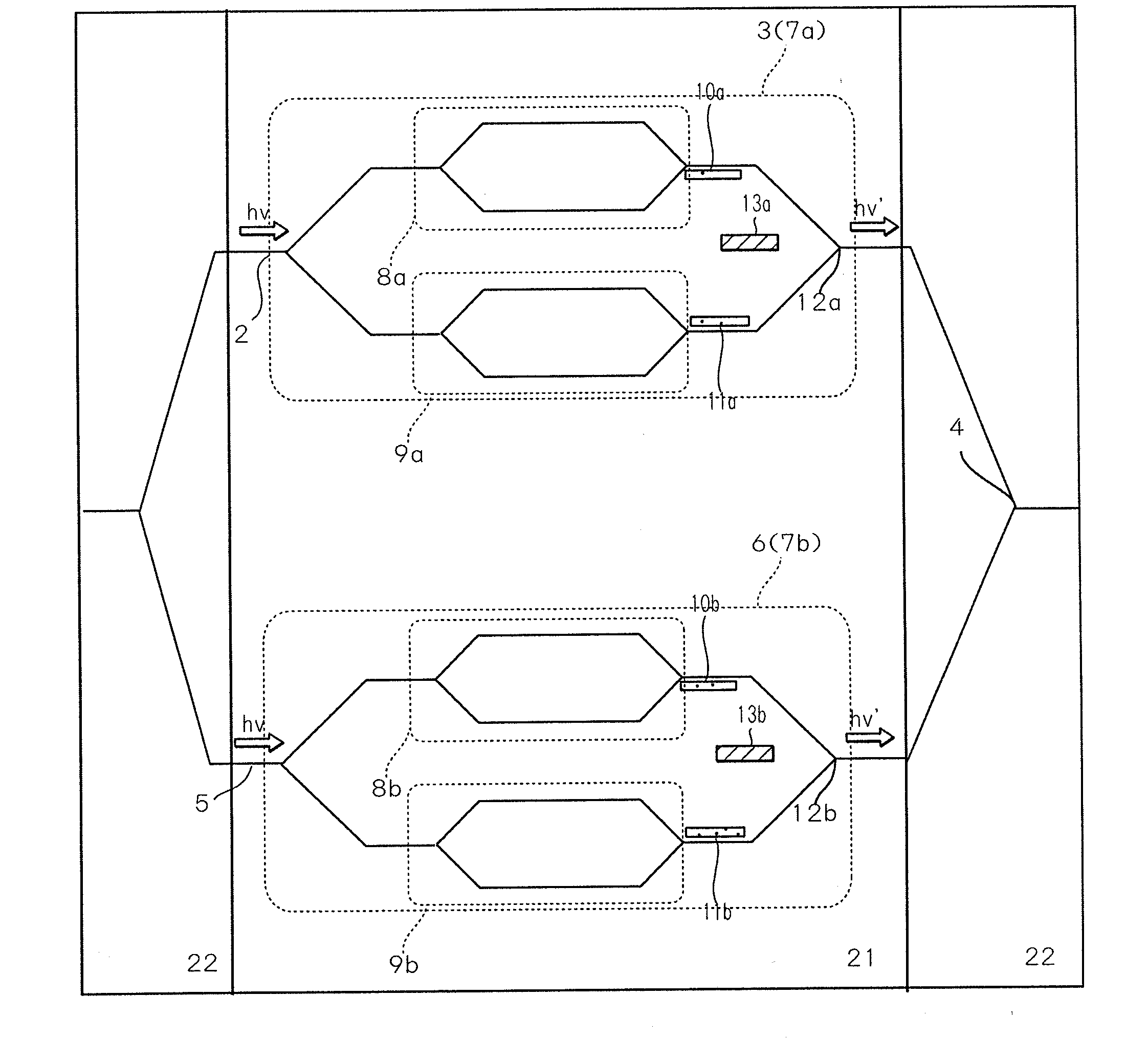
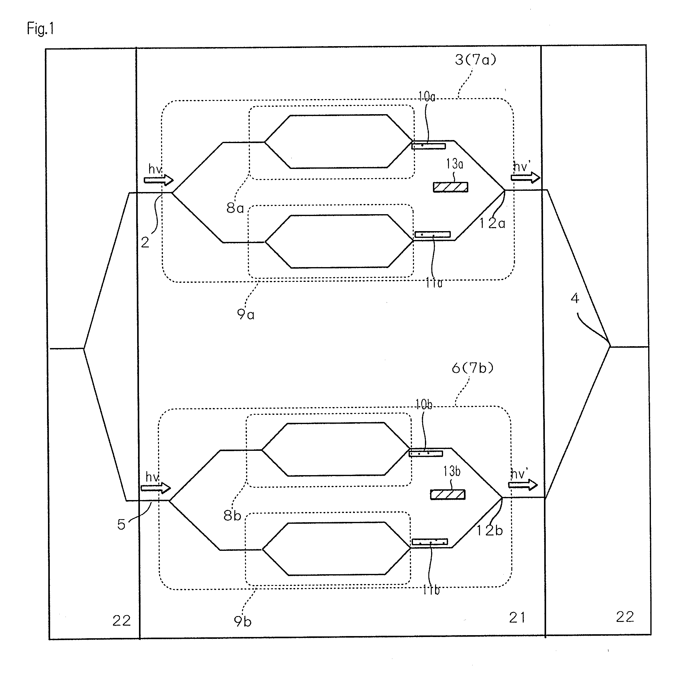
[0094]As shown in FIG. 5, in the present example, using the optically connected LiNbO3 waveguides and silicon-based PLC (planar lightwave circuit), a modulator comprising a QPMZM (quadruplex parallel MZMs) for 16 QAM modulation was manufactured. This QPMZM was manufactured by arranging four MZMs (MZM-I, MAM-Q, MZM-i, and MZM-q) in parallel. In other words, this QPMZM was provided with two DPMZMs (dual parallel MZMs). Each MZM was provided with traveling-wave-type electrodes (RFa1, RFb1, RFa2, and RFb2). As shown in FIG. 5, the QPMZM was further provided with six bias electrodes for controlling the phase offset between the MZMs. The input and output of the two DPMZMs were coupled to PLC-based optical couplers at their ends.

[0095]The electro-optic frequency response in each electrode is shown in FIG. 6. In FIG. 6, the modulation electrodes of the bandwidths of 3 dB and 6 dB were approximately 10 GHz and 25 GHz. In other words, it was found that this modulator can be us...

third example

Modulator for 50-Gb / s 16 QAM Modulation

[0096]FIG. 7 is a schematic diagram showing the configuration of the device used in the present example. Within a transmitter, the continuous light from an external cavity semiconductor laser diode (LD) was subjected to 16 QAM modulations by a QPMZM. Each arm of a modulator was push-pull-driven using the PRBS (pseudo random bit sequence) of 12.5 Gb / s binary NRZ (non-return-to-zero) with a data length of 29−1 generated by a commercial 4-channel pulse pattern generator (PPG). A pair of MZMs (MZM-I and MZM-Q) was driven within a range between −π to π in order to obtain large-amplitude QPSK signals. The remaining pair of MZMs was driven within a range of −π / 2 to π / 2 in order to obtain small-amplitude QPSK signals.

[0097]Within a receiver, a signal was demodulated using a digital homodyne wave detector. The digital homodyne wave detector combined a signal with local oscillator (LO) light using an optical hybrid coupler. For simplicity, the LO light w...


PUM


Abstract

A quadrature amplitude modulation (QAM) signal generator, which can obtain optical signals such as QAM signals without handling multilevel electrical signals, can be produced by using a plurality of parallel Mach-Zehnder modulators (MZMs), such as quadruplex parallel MZMs (QPMZM). The quadrature amplitude modulation (QAM) signal generator includes a first waveguide, a first quadrature phase-shift-keying (QPSK) signal generator provided on the first waveguide, a second waveguide connected with the first waveguide at a wave-combining point, and a second quadrature phase-shift-keying (QPSK) signal generator provided on the second waveguide.

Description

BACKGROUND OF THE INVENTION[0001]1. Field of the Invention[0002]The present invention relates to a quadrature amplitude modulation (QAM) signal generator.[0003]2. Description of the Related Arts[0004]Various multilevel optical modulation formats such as DQPSK (Differential-Quadrature Phase-Shift-Keying), QPSK (Quadrature Phase-Shift-Keying) in a coherent detecting system, APSK (Amplitude-and-Phase-Shift-Keying), and QAM (Quadrature-Amplitude-Modulation) have been developed for the purpose of improving the frequency utilization efficiency of channels for optical communications.[0005]Especially, DQPSK using dual parallel Mach-Zehnder modulators (DPMZM) is the most practicable and has received particular attention, since it can modulate the in-phase components (I components) of a carrier signal and the quadrature phase components (Q components) of the carrier signal independently by using the modulators. There has been developed a DQPSK signal generator that can generate an optical mod...

Claims


Application Information

Patent Timeline
IPC IPC(8): H04L27/18H04B10/12H04B10/00H04B10/50H04B10/516H04B10/54H04B10/556H04B10/61H04L27/36
CPCH04B10/5053H04L27/38H04L27/36H04B10/541H04B10/505H04B10/5561H04L27/2096
Inventor KAWANISHI, TETSUYASAKAMOTO, TAKAHIDECHIBA, AKITOTSUCHIYA, MASAHIRO
Owner NAT INST OF INFORMATION & COMM TECH
Why Eureka
Try Eureka