[0008]This need for a method for composite stack analysis for use in the design and manufacture of composite structures is satisfied and numerous advantages are discussed herein. Embodiments of the method may provide one or more of the following advantages: provides a method for evaluating the actual tow or tape distribution occurring at the ply level in relation to all of the plies below and above it in a composite stack or laminate; provides a method for analyzing a
composite structure for concentrations of imperfections or deviations from theoretical designs in a stack of plies or laminate that can
impact overall functionality but be allowable by specifications at the individual ply level; provides a method that can improve
composite structure design and manufacture, which in turn, can improve functional characteristics of composite structures used as structural components in aircraft and other structures, resulting in improved strength, reduced weight, better appearance, and consistency of production; provides a method for determining the
impact of manufacturing implementations of a design in a composite stack-up and for analyzing the progressive build-up of the manufacturing definitions of plies; provides a method for analyzing the interactions of plies in a composite stack-up at the detailed design and manufacturing level; provides a method that can allow for implementation of changes to the design and manufacture of composite structures early in the production environment; provides a method that can generate data allowing concurrent production environments to enhance the overall design, analysis and manufacturing aspects of composite structures; provides a method for optimization of composite structure designs that are manufactured using automated
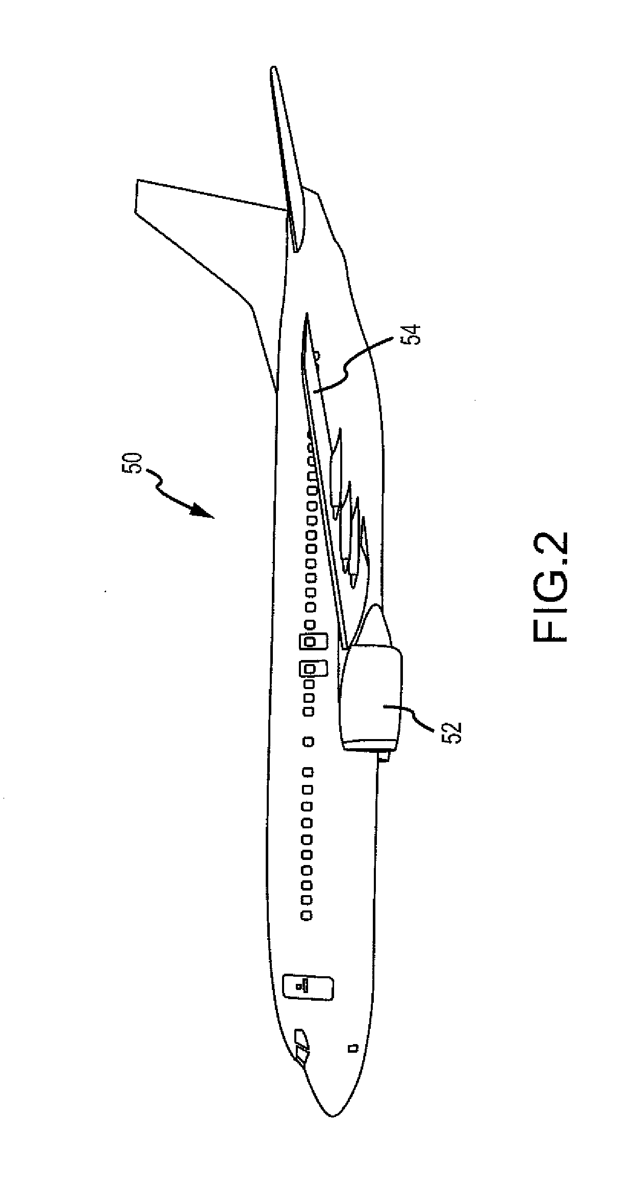
fiber placement or tape laying techniques, and that may be used in such structures as aircraft,
spacecraft,
watercraft, military craft, automobiles, trucks, buses, ships, bridges, rotor blades for aircraft, rotor blades for power generation, and other suitable structures.
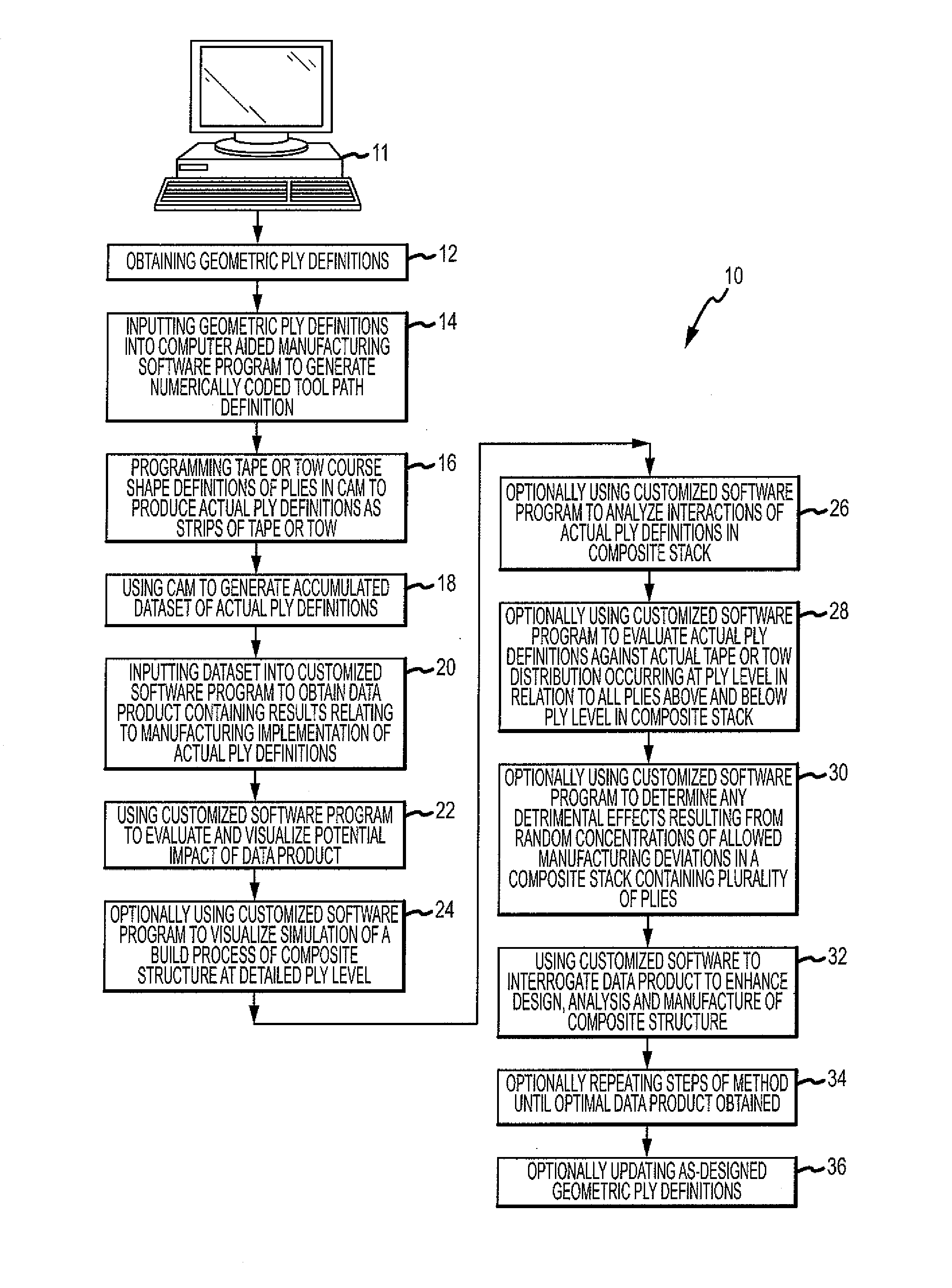
[0009]In one embodiment of the disclosure there is provided a method using a computer for generating a data product that allows for enhanced design, analysis and manufacture of a composite structure comprising a plurality of plies. The method comprises the step of obtaining geometric ply definitions from an
engineering source. The method further comprises the step of inputting the geometric ply definitions into a
computer aided manufacturing (CAM) software program to generate a numerically coded
tool path definition containing centerline data for each tape or tow course comprising a ply. The method further comprises the step of
programming tape or tow course shape definitions of a plurality of plies in the
computer aided manufacturing (CAM) software program to produce a plurality of actual ply definitions as strips of tape or tow courses. The method further comprises the step of using the
computer aided manufacturing (CAM) software program to generate an accumulated dataset of actual ply definitions. The method further comprises the step of using a customized software program to analyze the dataset to obtain a data product containing results relating to manufacturing implementation of the actual ply definitions. The method further comprises the step of using the customized software program to evaluate and visualize
potential impact of the data product. The method further comprises the step of using the customized software program to interrogate the data product in order to enhance design, analysis and manufacture of the composite structure.
[0010]In another embodiment of the disclosure, there is provided a method using a computer for generating a data product that allows concurrent production environments to enhance design, analysis and manufacture of a composite structure comprising one or more plies. The method comprises the step of obtaining geometric ply definitions from an
engineering source. The method further comprises the step of inputting the geometric ply definitions into a
computer aided manufacturing (CAM) software program to generate a numerically coded
tool path definition containing centerline data for each tape or tow comprising a ply. The method further comprises the step of
programming tape or tow course shape definitions of a plurality of plies in the
computer aided manufacturing (CAM) software program to produce a plurality of actual ply definitions as strips of tape or tow. The method further comprises the step of using the computer aided manufacturing (CAM) software program to generate an accumulated dataset of actual ply definitions. The method further comprises the step of inputting the dataset into a customized software program to obtain a data product containing results relating to manufacturing implementation of the actual ply definitions. The method further comprises the step of using the customized software program to evaluate and visualize
potential impact of the data product. The method further comprises the step of using the customized software program to visualize a
simulation of a build process of the composite structure at a detailed ply level. The method further comprises the step of using the customized software program to analyze interactions of the actual ply definitions in a composite stack. The method further comprises the step of using the customized software program to evaluate the actual ply definitions against actual tape or tow distribution occurring at a ply level in relation to all plies above and below the ply level in a composite stack. The method further comprises the step of using the customized software program to determine any detrimental effects resulting from random concentrations of allowable manufacturing deviations in a composite stack containing a plurality of plies. The method further comprises the step of using the customized software program to interrogate the data product in order to enhance design, analysis and manufacture of the composite structure. The method further comprises the step of repeating the steps of the method until an optimal data product is obtained. The method further comprises the step of updating as-designed geometric ply definitions.
[0011]In another embodiment of the disclosure, there is provided a method using a computer for analyzing interactions of plies in a composite structure. The method comprises the step of inputting theoretical ply definitions into a computer aided manufacturing software program to generate output data comprising tape or tow course definitions of a plurality of plies. The method further comprises the step of programming the tape or tow course definitions in the computer aided manufacturing (CAM) software program to produce a plurality of actual ply definitions. The method further comprises the step of using the computer aided manufacturing (CAM) software program to generate an accumulated dataset of actual ply definitions. The method further comprises the step of inputting the dataset into a customized software program to obtain one or more characteristics relating to manufacturing implementation of the actual ply definitions. The method further comprises the step of using the customized software program to evaluate and visualize potential
impact of the manufacturing implementation in terms of the one or more characteristics. The method further comprises the step of using the customized software program to interrogate the one or more characteristics in order to enhance design, analysis and manufacture of the composite structure.

