
Method of manufacturing a magnetic disk

a manufacturing method and magnetic disk technology, applied in the manufacture of head surfaces, record carriers, coatings, etc., can solve the problems of thermal stability degradation of recorded signals, loss of recorded signals, and impediment to the increase of recording density of magnetic disks, so as to reduce magnetic spacing, increase recording density, and high reliability

Inactive Publication Date: 2010-08-19
WD MEDIA SINGAPORE PTE
View PDF8 Cites 69 Cited by
  • Summary
  • Abstract
  • Description
  • Claims
  • Application Information

AI Technical Summary

Benefits of technology

[0041]According to this invention, it is possible to provide a magnetic disk that can achieve a further reduction in magnetic spacing and that has high reliability even with the low flying height of a magnetic head following the rapid increase in recording density in recent years and with the very strict requirement for environmental resistance following the diversification of applications.

Problems solved by technology

However, in the case of conventionally commercialized magnetic disks of the in-plane magnetic recording type (also called the longitudinal magnetic recording type or the horizontal magnetic recording type), as a result of the reduction in size of magnetic crystal grains, there has been the occurrence of a thermal fluctuation phenomenon where the thermal stability of recorded signals is degraded due to superparamagnetism so that the recorded signals are lost.
This has been an impeding factor for the increase in recording density of the magnetic disks.

Method used


Image

  • Method of manufacturing a magnetic disk
  • Method of manufacturing a magnetic disk
  • Method of manufacturing a magnetic disk

Examples


example 1

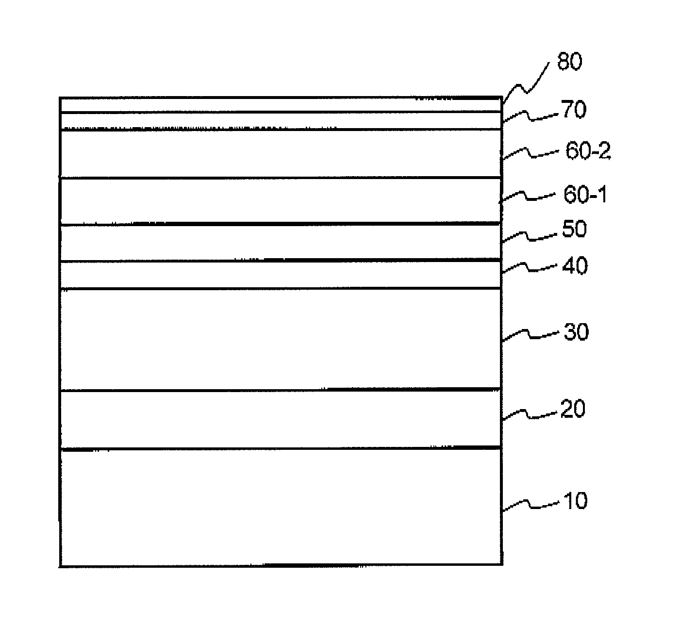
[0078]Referring to FIG. 1, a magnetic disk according to Example 1 of this invention has an adhesive layer 20, a soft magnetic layer 30, a first underlayer 40, a second underlayer 50, magnetic layers 60-1 and 60-2, a carbon-based protective layer 70, and a lubricating layer 80 which are formed in this order over a disk substrate 10.

[0079](Preparation of Lubricant)

[0080]As a lubricant, use was made of a commercial perfluoropolyether-based lubricant, Fomblin Z-Tetraol (trade name) manufactured by Solvay Solexis, Inc., having been subjected to molecular weight fractionation by the GPC method to have Mn of 3,000 and a molecular weight dispersion of 1.08.

[0081](Manufacture of Magnetic Disk)

[0082]A 2.5-inch glass disk (outer diameter: 65 mm, inner diameter: 20 mm, disk thickness: 0.635 mm) made of a chemically strengthened aluminosilicate glass was prepared as the disk substrate 10. The main surface of the disk substrate 10 was mirror-polished to Rmax of 2.13 nm and Ra of 0.20 nm.

[0083]On ...

example 2

[0100]A lubricating layer was formed in the following manner.

[0101]There was prepared a solution in which a lubricant prepared in the same manner as in Example 1 was dispersed and dissolved in a fluorine-based solvent, HFE7600 (trade name) manufactured by Minnesota Mining and Manufacturing (3M) Company, which corresponds to the above-mentioned exemplified solvent 2, at a concentration of 0.2 wt % at a liquid temperature of 45° C. Using this solution as a coating solution, a magnetic disk formed with layers up to a protective layer was immersed therein and coated therewith by the dipping method, thereby forming the lubricating layer. No coating unevenness occurred.

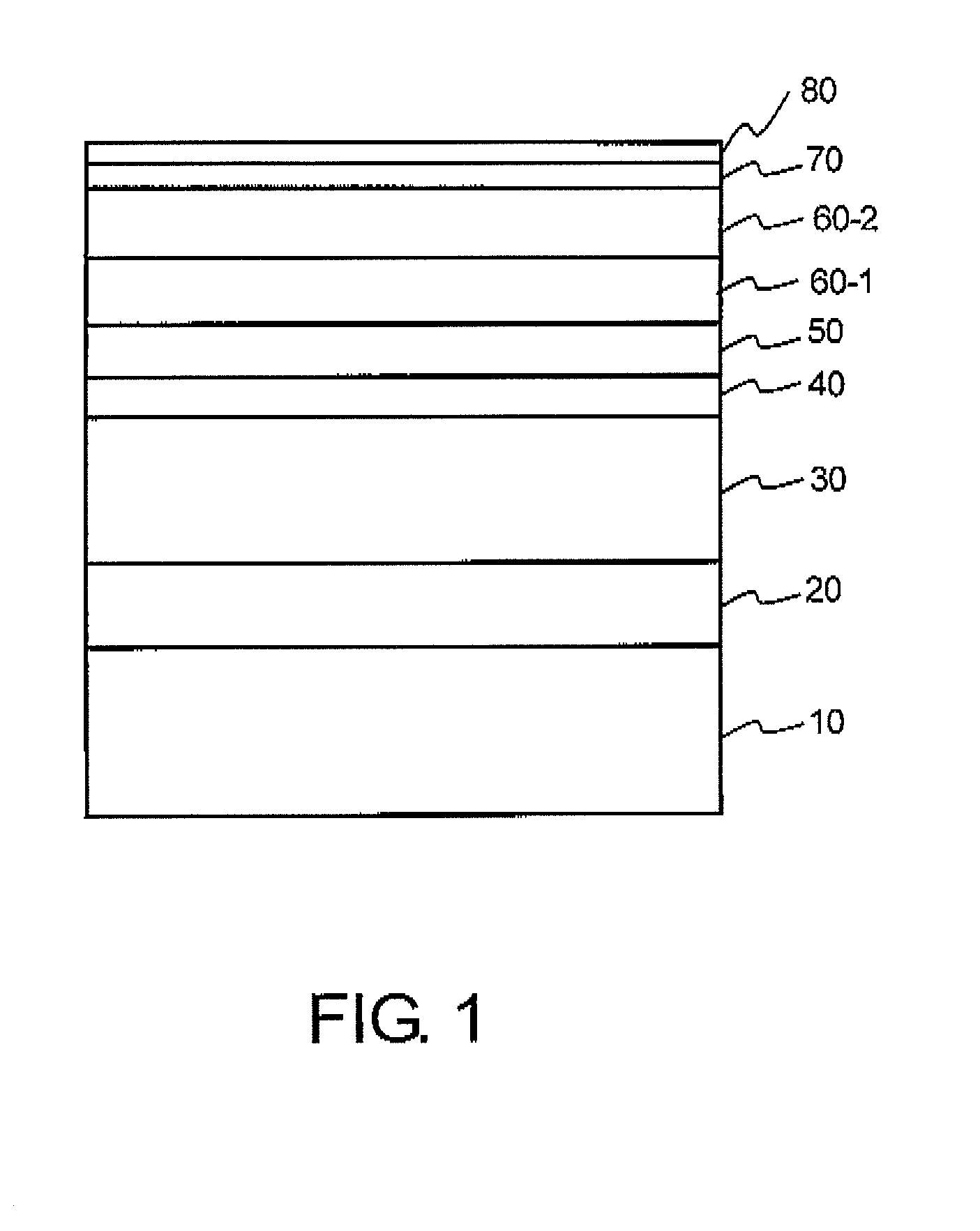
[0102]After forming the lubricating layer, the magnetic disk was heat-treated at 130° C. for 90 minutes and subjected to ultraviolet irradiation. The thickness of the lubricating layer was measured by a Fourier transform infrared spectrophotometer (FTIR) and it was 15 Å. Accordingly, the magnetic disk of Example 2 was obtai...


PUM


Abstract

On manufacturing a magnetic disk having at least a magnetic layer (60), a protective layer (70), and a lubricating layer (80) formed in this order over a substrate (10), the lubricating layer is formed by using a coating solution in which a perfluoropolyether compound having a perfluoropolyether main chain and a hydroxyl group in a structure thereof is dispersed and dissolved in a fluorine-based solvent having a boiling point of 90° C. or more.

Description

[0001]This application is based upon and claims the benefit of priority from Japanese Patent Application No. 2009-036068, filed on Feb. 19, 2009, and Japanese Patent Application No, 2010-033277, filed on Feb. 18, 2010, the disclosures of which are incorporated herein in their entirety by reference.TECHNICAL FIELD[0002]This invention relates to a method of manufacturing a magnetic disk adapted to be mounted in a magnetic disk apparatus such as a hard disk drive (hereinafter abbreviated as a HDD).BACKGROUND ART[0003]Various information recording techniques have been developed following the increase in volume of information processing in recent years. Particularly, the areal recording density of HDDs using the magnetic recording technique has been increasing at an annual rate of about 100%. Recently, the information recording capacity exceeding 250 GB has been required per 2.5-inch magnetic disk adapted for use in a HDD or the like. In order to satisfy such a requirement, it is necessa...

Claims


Application Information

Patent Timeline
IPC IPC(8): G11B5/187
CPCG11B5/8408G11B5/82
Inventor SHIMOKAWA, KOICHIHAMAKUBO, KATSUSHIITOH, KAE
Owner WD MEDIA SINGAPORE PTE
Learn More