Method of manufacture of a dual alloy impeller

a manufacturing method and technology of impeller, applied in the direction of machines/engines, solid-state devices, non-electric welding apparatuses, etc., can solve the problems of increased demands on engine components and materials, increased pressure on the compressor stage tip speed and bore stress, and high compressor discharge temperature, so as to improve strength and oxidation resistance

Inactive Publication Date: 2010-08-26
HONEYWELL INT INC
View PDF28 Cites 19 Cited by
  • Summary
  • Abstract
  • Description
  • Claims
  • Application Information

AI Technical Summary

Benefits of technology

[0010]In one embodiment, and by way of example only, there is provided a method for fabricating a machinable structure comprising the steps of: providing a bore sub-element comprising a γ / γ′ powder metal (PM) nickel based superalloy; providing a body sub-element comprising a nickel aluminide intermetallic based alloy, the nickel aluminide intermetallic based alloy having improved strength and oxidation resistance when exposed to temperatures in a range of between about 1250° F. to about 1500° F., that is greater than a strength of the γ / γ′ powder metal (PM)nickel based superalloy, when the γ / γ′ powder metal (PM) nickel based superalloy is exposed to temperatures in the range; contacting the bore sub-element and the body sub-element; joining the bore sub-element and the body sub-element; and machining to define the machinable structure.

Problems solved by technology

The harsh operating conditions of high temperature and pressure that are now frequently projected place increased demands on engine components and materials.
Relatively higher compression ratios in turn result in high compressor discharge temperatures.
A reduced number of compression stages to accomplish higher compression ratios results in higher compressor stage tip speeds and higher bore stresses.
These combined demands have made it very difficult to utilize monolithic alloy impellers for high pressure compressor (HPC) stages of gas turbine engines.

Method used


Image

  • Method of manufacture of a dual alloy impeller
  • Method of manufacture of a dual alloy impeller
  • Method of manufacture of a dual alloy impeller

Examples


Embodiment Construction

[0022]The following detailed description of the invention is merely exemplary in nature and is not intended to limit the invention or the application and uses of the invention. Furthermore, there is no intention to be bound by any theory presented in the preceding background of the invention or the following detailed description of the invention. Reference will now be made in detail to exemplary embodiments of the invention, examples of which are illustrated in the accompanying drawings. Wherever possible, the same reference numbers will be used throughout the drawings to refer to the same or like parts.

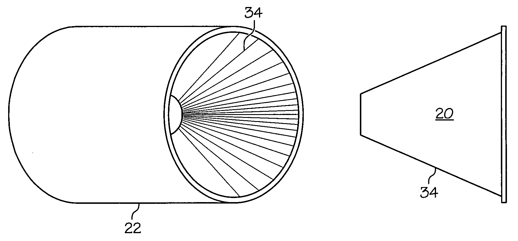
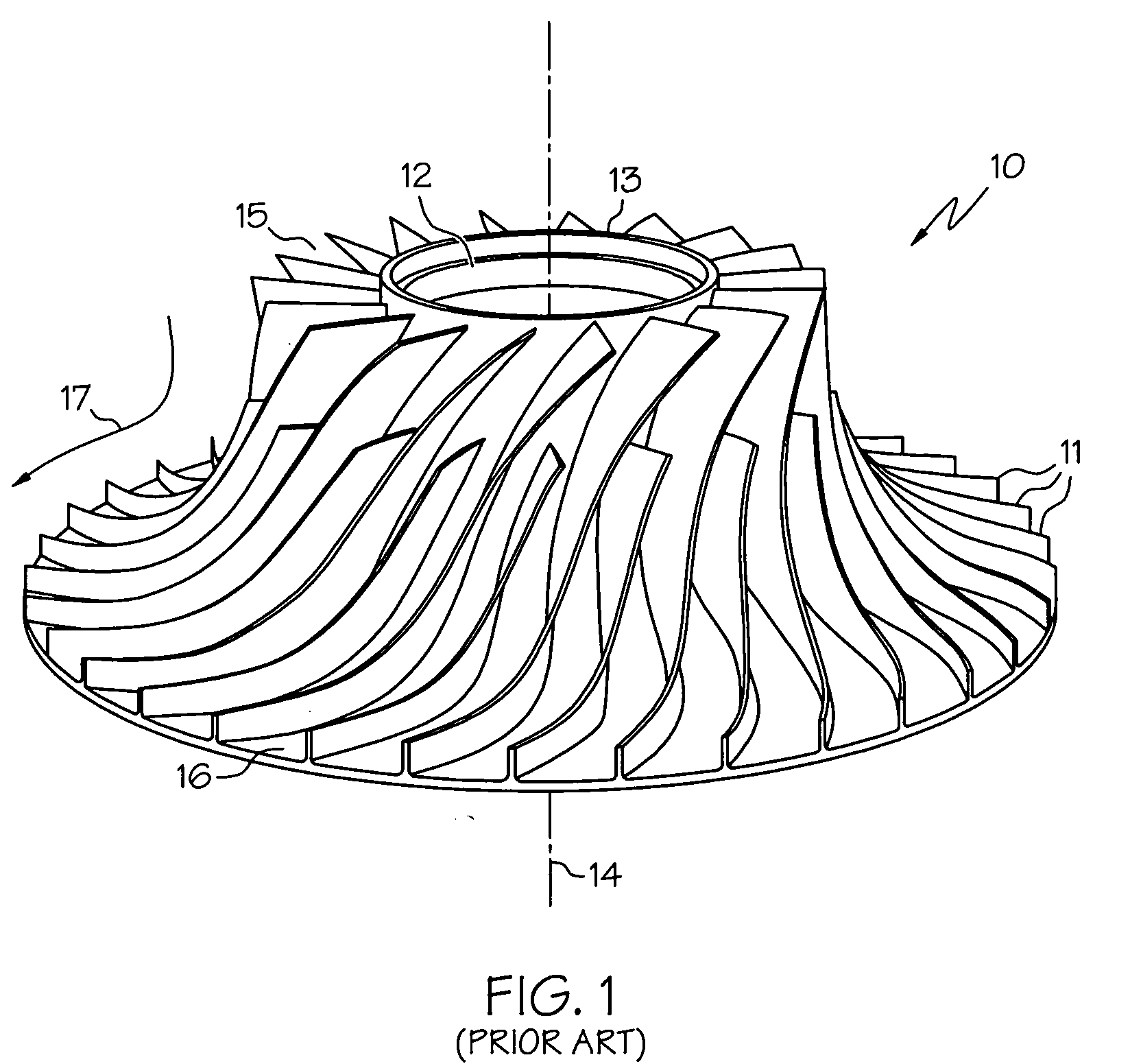
[0023]Referring now to FIG. 1 there is shown a representation of a typical impeller suitable for use with the present invention. An impeller 10 includes a plurality of impeller airfoils 11 attached to a central core 12. The impeller 10 has a generally radial structure and, as shown in FIG. 1, a central bore area 13. In some designs, the impeller 10 is fabricated as a unitary piece wi...


PUM

PropertyMeasurementUnit
temperaturesaaaaaaaaaa
operating temperaturesaaaaaaaaaa
temperaturesaaaaaaaaaa

Abstract

There is provided a method for fabricating a dual alloy structure that may in turn be machined to fabricate a rotary component for use in a gas turbine engine. The method provides a powder metal (PM) nickel based superalloy and a nickel aluminide intermetallic based alloy. The powder metal (PM) nickel based superalloy displays characteristics, such as improved strength, low cycle fatigue resistance, fracture toughness, and crack growth resistance. The nickel aluminide intermetallic based alloy displays characteristics, such as high temperature creep and oxidation resistance, suitable for use in the outer radial area of an impeller. A bore sub-element is fabricated from the powder metal (PM) nickel based superalloy. A body sub-element is fabricated from the nickel aluminide intermetallic based alloy. The bore sub-element and body sub-element are joined by inertia welding or diffusion bonding at a common mating surface.

Description

TECHNICAL FIELD[0001]The present invention relates to methods and materials for manufacturing gas turbine engine components. More particularly the invention relates to improved methods and materials with which to manufacture impellers and impeller-like rotating components comprising more than one alloy.BACKGROUND[0002]In an attempt to increase the efficiencies and performance of contemporary jet engines, and gas turbine engines generally, engineers have progressively pushed the engine environment to more extreme operating conditions. The harsh operating conditions of high temperature and pressure that are now frequently projected place increased demands on engine components and materials. Indeed the gradual change in engine design has come about in part due to the increased strength and durability of new materials that can withstand the operating conditions present in the modern gas turbine engine.[0003]The compressor stage of the gas turbine engine is one area that has seen increas...

Claims


Application Information

Patent Timeline
Patent Type & Authority Applications(United States)
IPC IPC(8): B32B15/01B22F1/00B22F3/15B23K20/12B23K20/00
CPCB22F5/04Y10T428/12944B23K20/021B23K2201/001B22F9/082C22C1/0433C22C1/0491B22F2998/10B22F7/062Y10T428/12229Y10T428/12493F04D29/284F04D29/023B22F3/15B22F2003/247B22F3/20B22F3/17F05D2300/609F05D2230/42F05D2230/236F05D2230/239F05D2300/173F05D2300/175F05D2230/10F05D2300/502F05D2230/25F05D2230/24B23K2101/001C22C1/047
Inventor RICE, DEREK ANTHONY
Owner HONEYWELL INT INC
Why Eureka
Try Eureka